Stop 3D Printing Failures With All3DP’s Ultimate Guide to Support Structures

Confidently tackle overhangs and bridges in your models with All3DP's ultimate guide to 3D printing support structures.
If you’ve had any experience with an FDM 3D printer, you’ve probably come across one or two occasions where you needed to make use of support structures. If you’ve ever had doubts, worries, or even full-blown print failures because of them, that ends now. This guide is all you need to know about support structures to feel confident using them, start to finish.
Support structures are considered a necessary evil in 3D printing. They are absolutely essential for models with nasty overhangs or bridges, but they can frustrate by increase material costs, adding more post-processing work, and sometimes even damaging the model’s surface. Getting supports right is, therefore, a very important aspect of 3D printing complicated models.
This article breaks down every aspect of 3D printing support structures, from the types to the slicer settings, so you can print armed with the knowledge and confidence to get perfect 3D prints. Let’s get to it.
Support Structures: Nothing to Fear
A lot of 3D printing’s rougher edges have been smoothed out over the last few years. The introduction of new technology and a greater focus on user experience from manufacturers has left many with a much simpler, more intuitive, and refined experience.
Support structures used to leave many 3D printing uncomfortable. They were something a bit scary and basically, you didn’t want to have to deal with them. Their reputation of being difficult to deal with preceded them, so they’d be avoided if possible.
Things have got a lot better now though, especially with new technologies like material management systems and better software. A good example of how things have changed lies with the common support material PVA. This water-loving filament was something you’d only break out briefly for prints, and probably only if you had a dual-extruder too. Nowadays though, you can store it in a temperature and humidity-controlled material management system and have it hooked up to your 3D printer at all times, alongside your other filaments of choice, to be ready to go at a moment’s notice.
It’s also likely that with improved software options, that automatically applied supports (with options chosen for your model applied) will suffice for a solid print. With filaments already hosted in controlled environments and connected to the printer, it’s quite plausible you’ll be able to print your model, fully supported, directly through the slicer with just a few simple clicks of the mouse.
That doesn’t mean we won’t go into the ins and outs of supports here though. Not everyone has the flashy new tech. Not everyone wants to, either.
Either way, support structures should be nothing to fear. This guide will cover you, so you can go into the process of printing with them calm and confident.
Support Structures: What They Are & When You Need Them
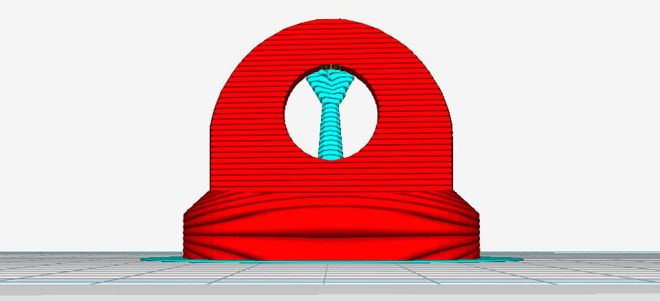
FDM 3D printers work by depositing layer over layer of thermoplastics to create a 3D object. Because of that, each new layer must be supported by the layer beneath it. If your model has an overhang or bridge unsupported by anything below, there’s a good chance it will drop or even fall. To prevent this disaster occurring, you’ll need additional 3D printed support structures to ensure a successful print.
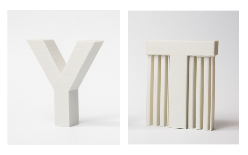
Here are some examples of overhangs and bridges illustrated with the help of the letters Y, H, and T.
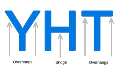
Overhangs: The 45 Degree Rule
Good news – not all overhangs need to be supported. The general rule of thumb is if an overhang tilts at an angle less than 45 degrees from the vertical, then you may be able to print that overhang without using supports.
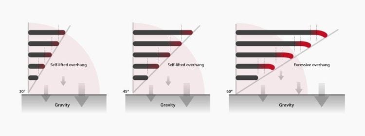
This aspect is best illustrated with the letters Y and T. The two overhangs in the letter Y have an angle below 45 degrees. Therefore, if you want to print the letter Y, you can get away without using supports.
You’ll also come across FDM 3D printer manufacturers saying that their machines are able to print higher overhang angles by default. This could be because their machines come with advanced process parameters and more capable hardware. However, this doesn’t mean that the same result can’t be achieved by a “standard” printer and a knowledgeable operator.
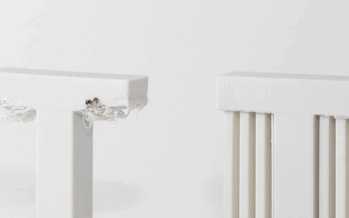
Bridges: The 10 mm Rule
As with overhangs, not all bridges require support. The rule of thumb here that if a bridge is less than 10 mm in length, the printer may be able to print it without supports.
To do this, the printer uses a technique called bridging – where it stretches the hot material for short distances and prints it to minimize sagging.
Once again, this distance should only be regarded as a general rule of thumb. Parameter adjustments, especially active cooling and print speed, can greatly improve bridging results that can extend far beyond the 10 mm threshold. If you want to know which settings to tweak, check out our 6 tips for perfect bridges.
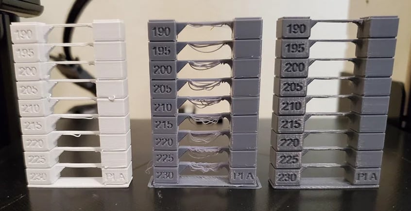
Test Your Printer’s Capabilities
Both rules of thumb regarding overhangs and bridges are just that – rules of thumb. Much depends on your printer, its condition, and the material you are using. Printers in bad condition may fail to print overhangs at an angle of 35 or 40 degrees from the vertical, while well-calibrated printers can deal with more extreme overhangs and bridges. Therefore, before you start printing models it is good practice to get an idea of your printer’s ability to print them.
Thankfully, this is quite easy to do. For overhangs, just download and print this overhang test model. This model has a series of overhangs ranging from 20 to 70 degrees at 5-degree increments. To test bridging, this shell-shaped design will show how far the envelope can be pushed. Alternatively, you can always use general print calibration models that also include bridges and overhangs.

Compare the dimensional accuracy and surface quality of the resulting parts to identify the angle where the printer starts failing. This is the maximum overhang angle or bridging distance that your printer can print without support at the chosen settings. Note this down so that you can use this information later to decide where to use support and where not to.
Support Structure Geometry
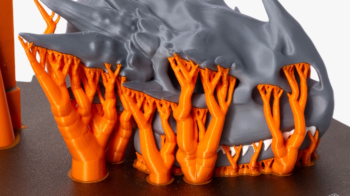
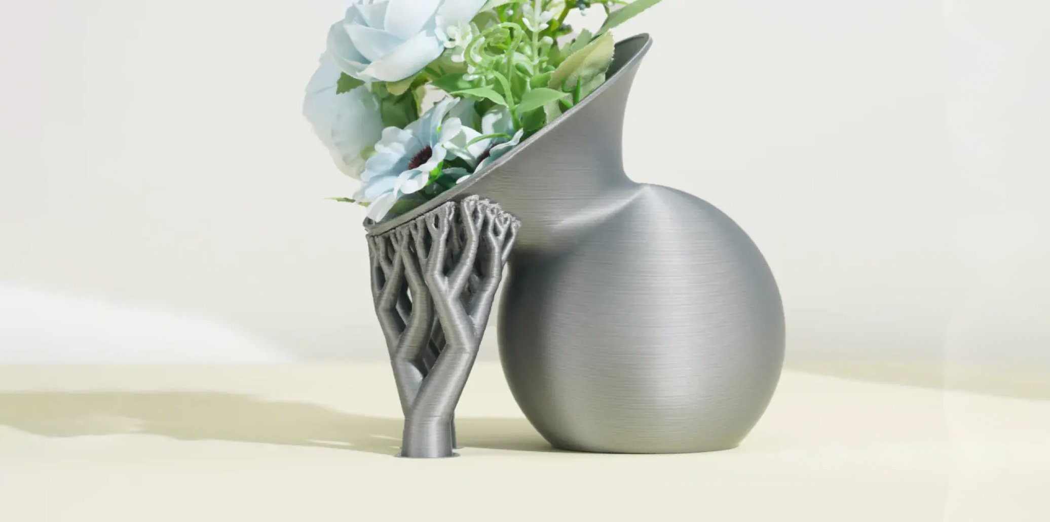
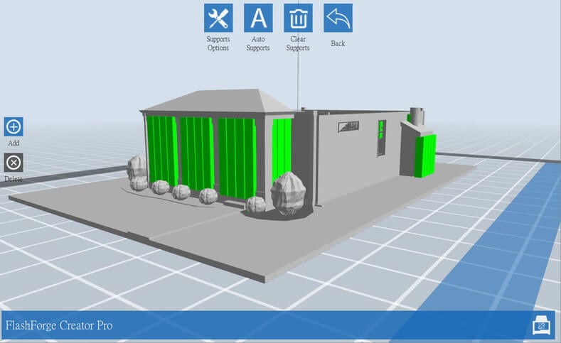
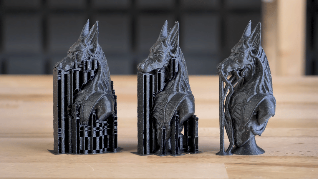
There are two common types of support structure — lattice and tree-like — with one extra support structure using a bit of both, known as hybrid supports.
Lattice Support
Also known as linear, these are the most common type of support used in 3D printing. They consist of vertical pillars that touch the entirety of the overhang. This type of 3D printing support works for just about every overhang and bridge. However, they are much harder to remove and much more likely to cause damage to the model surface.
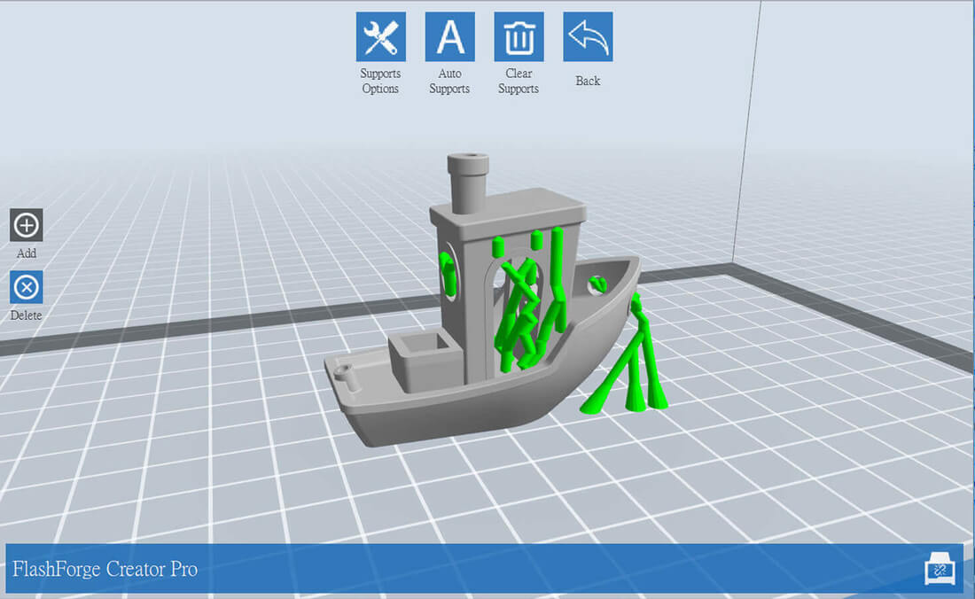
Tree-like support
Tree-like supports look like their name suggests. This type of 3D printing support only touches the overhang at certain points.
Hybrid Support
There’s nothing particularly complicated to hybrid supports. The software simply makes use of both linear and tree-like supports in order to provide the best of both worlds for the model.
You might need the strong, stable linear supports for some big overhangs in one part, but rely on the lightweight, easy-to-remove in other sections. Hybrid support means you can do this, and get the benefit of using both instead of just one.
Different slicers express themselves in different ways, and as we can’t explain every single one here without writing an entire white paper, we recommend checking out these three guides to some of the most popular slicers:
Types of Support by Ease of Removal
Break-away Supports
Printers with one extruder use break-away supports structures by default.
When you have one extruder, you have to use the same material that’s being used to print the model for printing support structures. You can naturally adjust the density of the support structures and make them much lower than the model density, but that’s the only control you have as far as support material is concerned.
Since the model and the supports are made of the same material, the only way to separate them is by either breaking off the support structure by hand or by carefully cutting it off with a knife.
These methods of removal introduce the risk of damaging the model, and you have to apply proper technique, and caution during the removal phase.
Dissolvable Supports
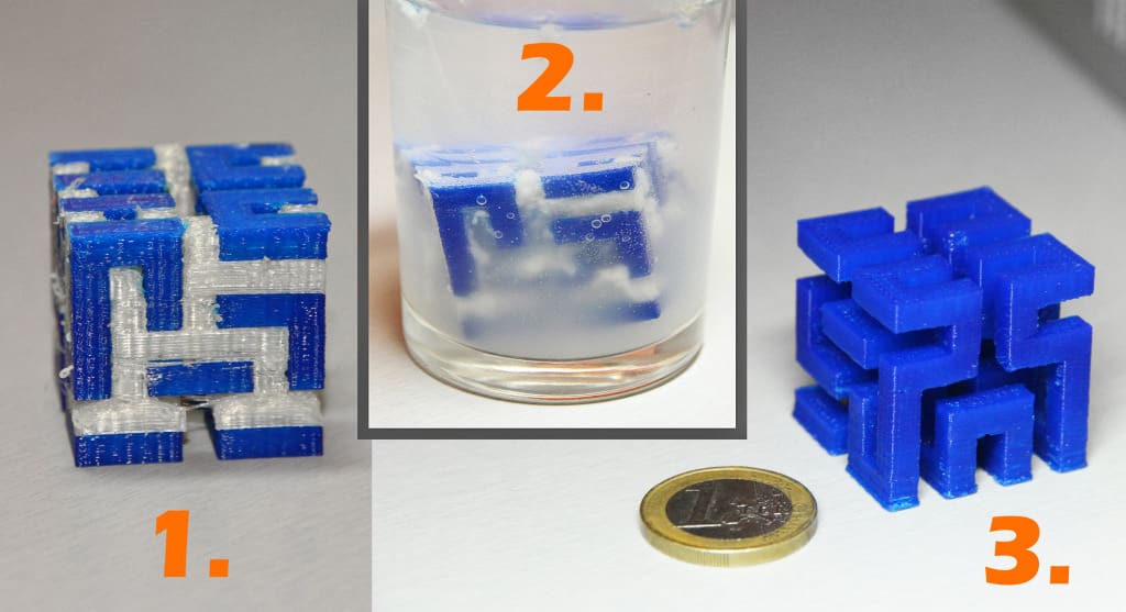
If you have a printer with two extruders, there’s a better option. You can load one extruder with PLA for printing the model, and the other with a water-soluble material like PVA or HIPS for printing the support structures. Once printing is over, simply wash them away by immersing the model in water or Limonene.
This method of removal reduces the risk of model damage and makes the post-processing work easier, making it ideal for complex prints.
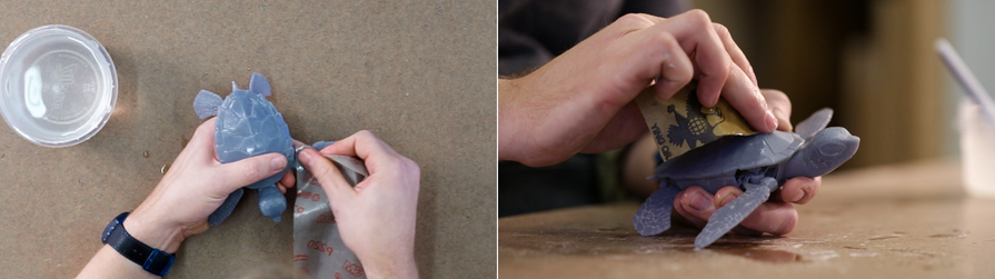
How to Remove Breakaway Supports
Since breakaway support structures are hard to remove and can potentially damage the model, some tried and tested tricks to remove them are encouraged.
- First, identify the support structures that are completely exposed and easy to maneuver with fingers. Try to break them away using your fingers. Be gentle. If you do this right, most of the support structure should come off pretty easily.
- Next, use a tool for removing the support structures that are hard to access. There are lots of opinions about which tools work best. You may use a needle nose plier, a putty-type knife, or a utility knife. You can also use a combination of all of these tools too.
- When using a knife or scraper, it’s a good idea to heat the model or the blade. This makes the support structures easier to slice. A tiny butane torch can help, but make sure that you don’t damage the model with it.
- Be very careful with utility knives – they’re very sharp.
- Sandpaper is also a great tool for removal. Wet sanding with high grit sandpapers (220 to 1200) will remove the little bumps left behind after removal and also polishes the model. For best results, apply water to the part and sand in smooth, light motions until the desired surface quality is achieved.
Sanding doesn’t just work on resin-printed parts to achieve a better surface finish (Source: Formlabs) - PLA printed models may develop stress marks when the support structures break away from them, leading to scratches, marks, and blemishes. Nail polish varnish is a great tool for patching or covering up these imperfections. If discoloration occurs, you can try to carefully heat up the material with a heat gun to return it to its original color.
Minimize Supports Through Design
Integrate supports into the model
One trick to get around support structures is to add elements to the model that perform the same job. This technique has been used by sculptors for centuries, as Antonio Canova demonstrated below with his “Venus Vitrix” sculpture.

Here, the right arm is an overhang, but it is supported by the pillows. The left leg is another overhang, but this time the bunched togas act as the support.
Integrating support structures into the design is more of an art than a science. You need to come up with elements that simultaneously fit into the overall design and can support the overhangs or bridges. When done correctly, it enhances the beauty of the model and makes the print process free of support structures – saving time, money, and labor.
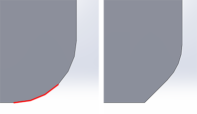
Chamfers
Another way to eliminate supports is chamfers. Chamfers are a neat way of turning otherwise nasty overhangs into innocuous overhangs with angles less than 45 degrees.
For example, if you have a gently sloping or curved edge, you can replace it with an angular edge that requires no support. Such an angular design is called a chamfer.
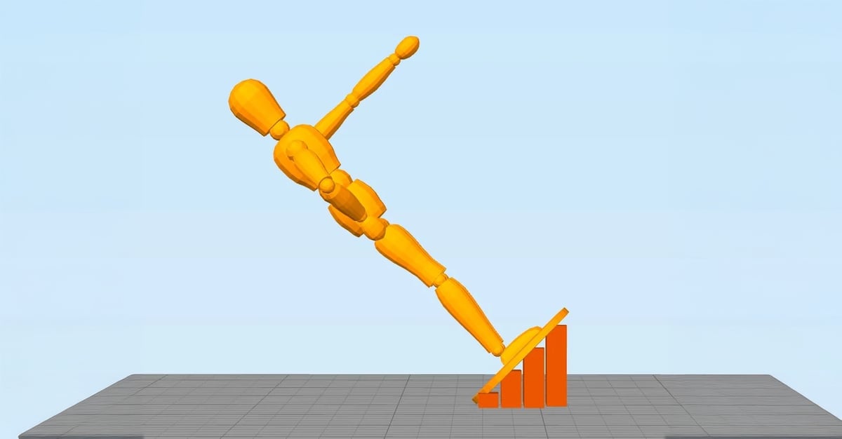
Minimize Supports Through Reorientation
Sometimes, minimizing the necessary support structures is as easy as reorienting the model on the print bed. For example, it is much better to print the open box shown below with the open face on the top.
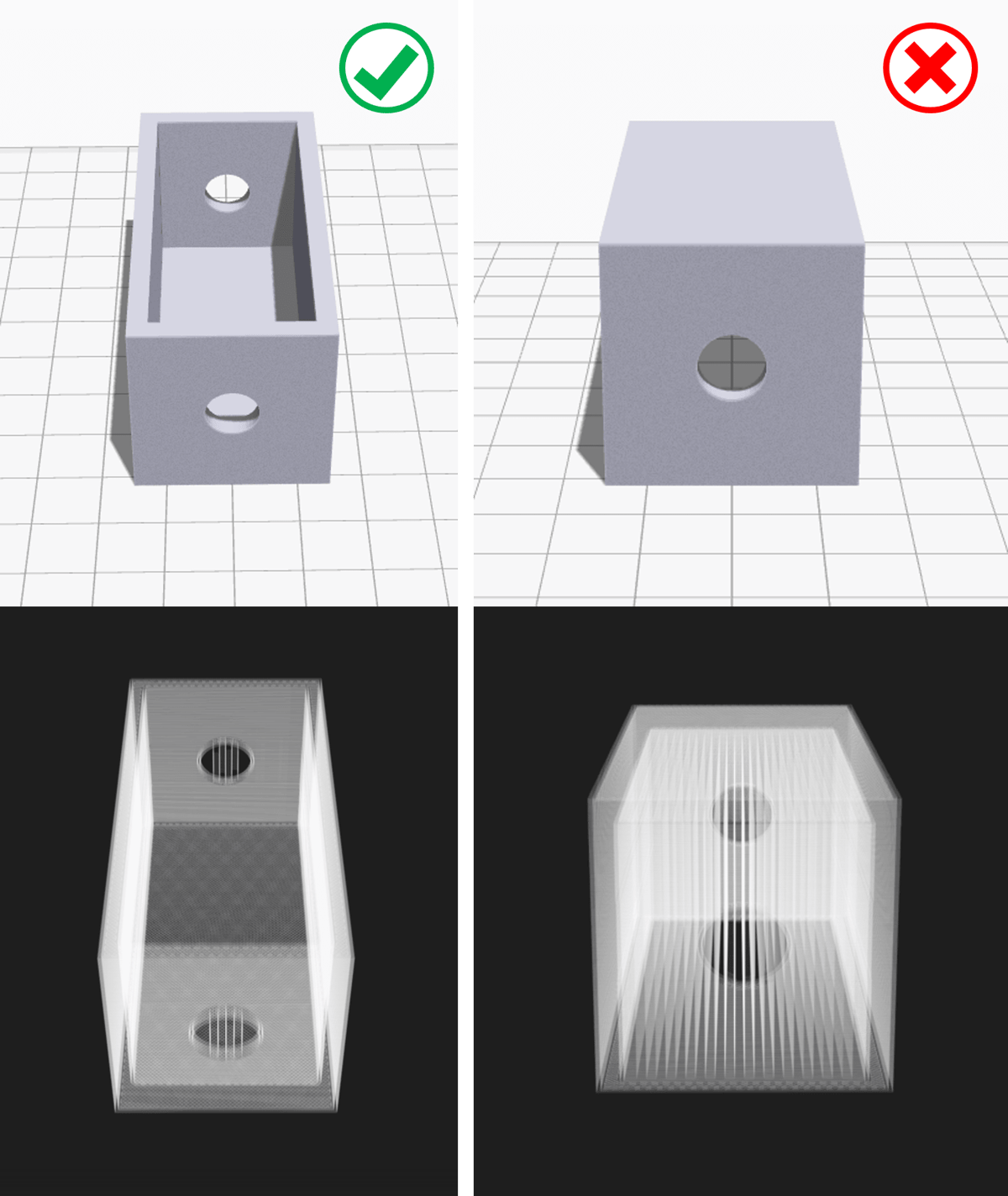
If you print the model as it is, we will need to support the left arm. It is basically a long overhang with an angle of 90 degrees.
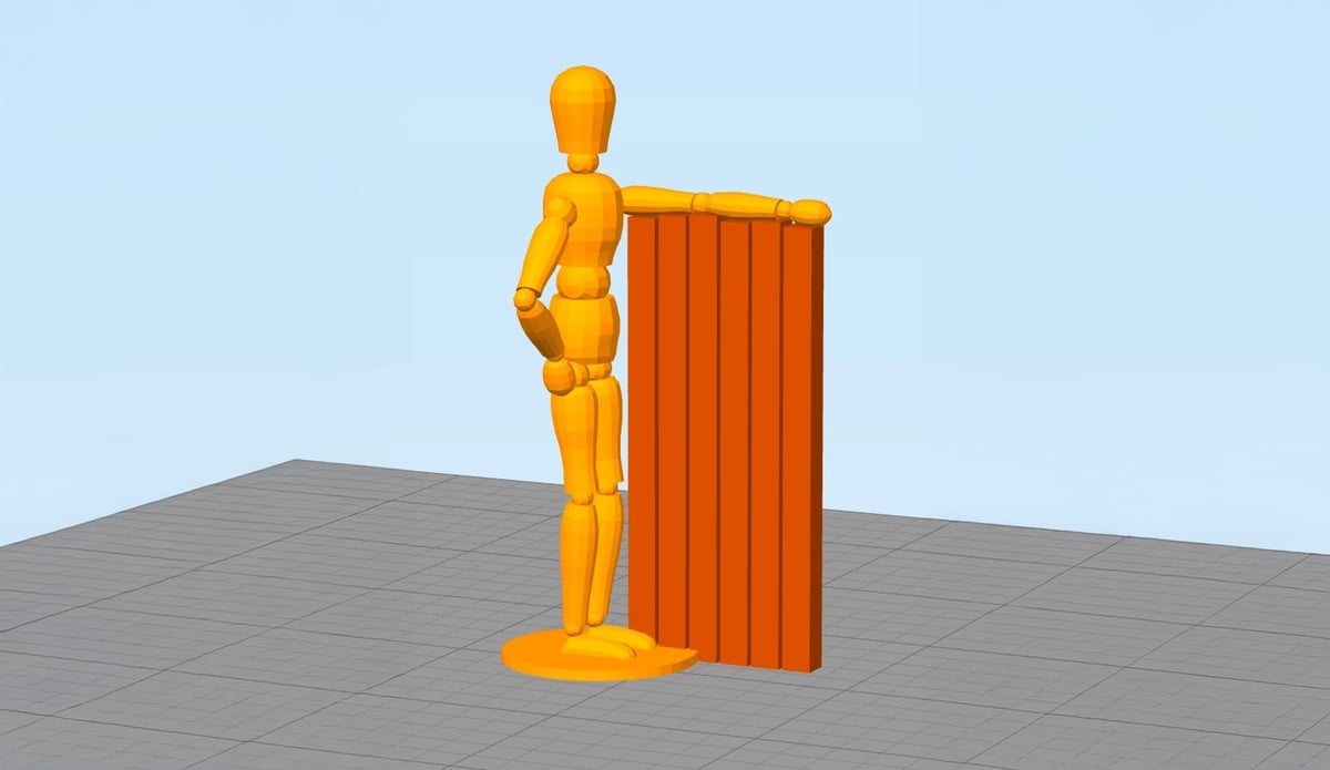
When you remove the supports, it will most likely leave blemishes on the underside of the arm. To avoid that, you can rotate the whole model by 45 degrees and just add support for the base of the model. The quality of the base of the model does not matter much anyway. This way, you can print the model with fewer support structures and save the left arm from damage.
This model is only a demonstration. More experienced makers among you will see the little “islands” at the knee, buttocks, and head where the print head would extrude into nothing and therefore result in a pretty ugly print. Of course, these islands would also need to be supported in order to avoid this.
Support-free Overhangs and Bridges
In the previous sections, we stressed you should try to minimize the use of support structures whenever possible. However, this implies that you will often be treading on tricky territory where there’s the risk of model instability. To minimize this risk, here are some general tricks.
- Make sure your 3D printer is optimally calibrated.
- Ensure that you are cooling your printing material as rapidly as possible. The longer it takes for your material to cool, the more likely it is that your bridge or overhang will deform or fail. Use your layer cooling fans aggressively. Also, lower your printing temperatures as much as possible.
- Reducing printing speed also helps to cool and it especially helps in printing longer bridges and tricky overhangs.
- If possible, try to use the lowest layer thickness. Lower layer thickness means less mass deposited on each run of the print head. This also helps cool the material faster.
Slicer Settings
Sometimes, it is impossible to avoid support structures. But even in this case, you should try your best to ensure that they’re stable, easily removable, don’t damage the surface of the model, and don’t waste a lot of material.
Your slicer software will give you a lot of additional ways to tweak support parameters. Most slicer software can generate them automatically, but they also provide a manual mode where you can add or remove supports wherever you want. Also, slicer software offers a lot of different settings that control the following aspects:
- Placement
- Strength
- Ease of removal after printing
- Damage to the print surface
In this article, we chose to focus on Cura, because it is one of the most popular free slicers out there. Although as we mentioned before, we recommend checking out these articles about Bambu Studio and PrusaSlicer for more detailed information on their setups too.
Cura offers a host of support structure-related settings under the “Support” section of the “Custom Settings”. If you can manipulate these settings properly, it is possible to create supports that meet most of the essential requirements.

You May Also Like:


Auto-generated Supports
First things first. How do you check if your model needs additional support?
Cura makes this easy. Once you have imported your model into Cura and positioned it on the virtual build plate, look out for sections colored in red. Those are the parts where Cura has detected overhangs.
If you see red on the bottom of the part where the model touches the build plate, you don’t have to worry about this area being unsupported. The build plate will take care of this problem. Small red areas at the tops of holes or between two structures are called bridges, and Cura will handle them automatically too.
If there are other parts highlighted in red, then you should pay attention to them. To begin with, you need to enable the auto-generated support structures to ensure that those red parts can be printed successfully. To do this, simply check the “Generate Support” checkbox under the “Support” section.
So, you have now enabled the auto-generated support structure, but probably didn’t see anything change in the model view. That’s because Cura does not show support structures in the default “Solid” view. To see the supports that were generated, change to “Layer” view. Support material (lines and volume) will be displayed in teal. Move the layer slider up and down to see where the support is added to the model.

Tree-like Or Linear Support
Cura generates lattice support structures by default. In version 3.2, Cura introduced the possibility of using tree-like supports instead of the default lattice ones.
Support Structure Placement
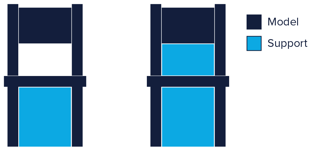
When you enable support structure, a setting called “Placement” automatically appears under the “Support” section. The “Placement” setting lets you coarsely control the positioning of the support structure. There are two options: “Everywhere” and “Touching Build Plate”. “Everywhere” is selected by default.
When “Everywhere” is selected, Cura attempts to build structures wherever they are necessary. This means you not only have support structures that are erected on the build plate but also those that use part of the model as its base. This is a reasonable option in most cases as this ensures that all unstable areas will have the necessary support.
However, if “Everywhere” is selected for very complicated models, the model might end up being completely encased by support material. If you don’t want this, simply change the placement setting to “Touching Build Plate”. This will create supports underneath overhanging sections of the model, only between the build plate and the model.
Enable Support Roof
Since a model’s overhang is printed on top of support structures, you don’t always get the best surface finish for these parts. The “Enable Support Roof” setting can help with that.
A support roof is a dense skin at the top of the support structure which does not compromise the surface finish of the overhangs too much. When you enable this setting in Cura using the checkbox, you will get a better finish quality. But this improvement comes at a cost as this option makes the support structures harder to remove than usual. Use this option only if the surface finish of the overhanging part is critical to the function of the finished part.
X/Y Distance Setting
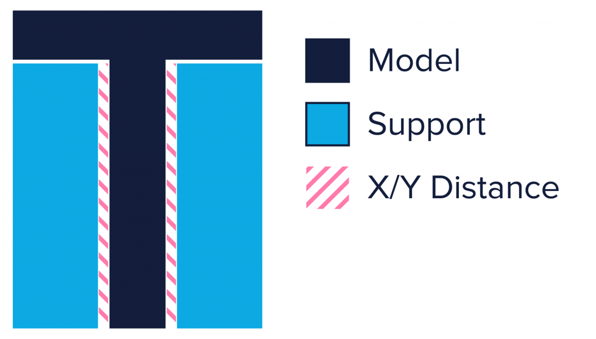
Sometimes, the supports are built too close to the model’s outer wall and leave marks on its outer surface. You can prevent this from happening by using the Support X/Y Distance hidden setting under the Support section.
The Support X/Y Distance setting in Cura essentially controls the minimum allowed distance between the model’s vertical walls and a support structure in the X/Y plane. If your support structures are damaging the walls or sticking to them, you can increase the value by increments of 0.2mm until the walls come out smooth. However, please ensure that there are no small overhangs sticking out of the outer walls that will go unsupported if you put a little bit of distance between the support and the walls.
Z-Distance Setting
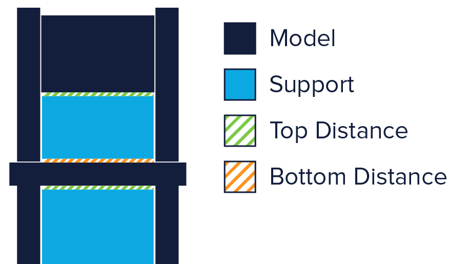
For the support material to break away cleanly without pulling the model layers apart, the connection between the support material needs to be made weaker than the connection between the layers of the model. Cura creates this weaker connection by leaving a space between the top and bottom of the support structure and the model – this space is known as Z-distance.
You can make the support structures easier to detach by controlling the hidden Z-distance settings under the “Support” section. The default value for this setting is the same as layer height. So if your layer height is 0.1 mm, the default Z-distance will be 0.1 mm too.
If your support material is difficult to break away from your model, increase this value in increments of your layer height until it comes away cleanly. Cura can either add support on any given layer or not add support. Unfortunately, there are no “half layers of support.” So if a 0.2 mm Z-distance setting for a print with a layer height of 0.1 mm is too much, and the Z-distance of 0.1 mm is not enough, you’re out of Z-distance options.
Support Types
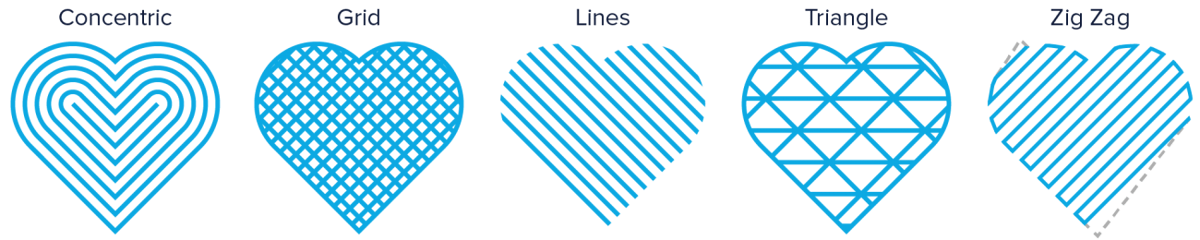
Cura generates 3D printing support material in one of seven patterns. You can change the pattern by using a hidden setting called Support Pattern under the Setting section.
In most cases, the default pattern, “Zig Zag”, will generate the best balance between strength and ease of removal. The other pattern options are “Triangles”, “Lines”, “Grid”, “Concentric”, “Concentric 3D”, “Cross”, and of course, tree support. If you are unhappy with the default pattern, you can experiment with the other options. Each of them will give you a different balance between strength and ease of removal. Community feedback has been mixed on which strategy works best since it’s dependent on part geometry and individual requirements.
Support Structures: The Downsides
As with anything in life, support structures have their downsides. There are a few to go through here, so allow us to explain.
Increased Material Cost
If you’re using 3D printing in a production setting, you probably only care about the cost per part. Same if you’re a hobbyist on a budget.
3D printed support structures obviously add to the production cost of the model. Support structures consume material, and this material is later removed and discarded. So, every bit of support material that you use is essentially waste, and adds to the cost of the print.
When printing with specialized materials like carbon-fiber-reinforced filaments, costs can quickly ramp up. It might be worth looking into material management systems or dual extruders that allow the machine to switch between different materials.
Increased Print Duration
Another cost factor to consider is the increased print duration that comes with support structures. While FDM 3D printers do not cost a ton of money to operate, print times can quickly add up, especially when it comes to volume production.
On the other hand, minimizing support structures may not always be the quickest solution. If you want a one-off part it might make more sense to use more supports than theoretically needed for a successful first try rather than failing and having to print the same part several times.
How much it will cost therefore depends on how many parts you want to produce, how many supports are required, at what speeds you are printing them, and, how easily they can be removed.
Additional Post-processing
Support structures are not part of the model. They are used to support overhanging geometries during printing. This means that once printing is over, you have the additional task of removing the structures before the model is ready to go.
In a production setting, added work means added cost. This can add up further when support structures are in hard-to-reach places, do not easily separate from the actual part, or removing them causes parts of the model to break.
To minimize post-processing, you might want to consider switching to soluble supports. Alternatively, you might be able to get rid of them entirely by integrating supports into the design or reorienting the model.
Risk of Damaging the Model
All in all, there are significant downsides to using support structures. Therefore, here’s another rule of thumb: minimize the use of support structures and add them only where necessary. In later sections, we will show you how to apply this philosophy right from the CAD design phase leading all the way up to the printing phase.
License: The text of "Stop 3D Printing Failures With All3DP’s Ultimate Guide to Support Structures" by All3DP is licensed under a Creative Commons Attribution 4.0 International License.