FreeCAD is a 3D parametric modeling program designed for creating and customizing real-life objects. It’s completely free and open source, which makes it a great option for independent workers or teams that require affordable access to the same software for everyone.
The program is organized in workbenches, which provide different layouts of tools depending on the task at hand. This means you can do a lot with the same program, such as drafting, modeling, or assembling.
In this tutorial, we’ll model a simple storage chest, which can be 3D printed later on or left as a model. We’ll go over how the program is organized, how to use each of the necessary tools, as well as some advice in case you want to take the next step and 3D print it.
Setting Up
Downloading FreeCAD is very simple, you don’t need to register or take many steps. Simply go to theFreeCAD’s download page, then click the download button. FreeCAD works for Linux, MacOS, and Windows, so select your OS accordingly.
Once the program is downloaded, there are a few things to set up and familiarize yourself with before starting a new design.
Navigation Style
In FreeCAD, you can set the navigation style in a few different ways, with setups that resemble other programs in terms of hotkeys and the layout.
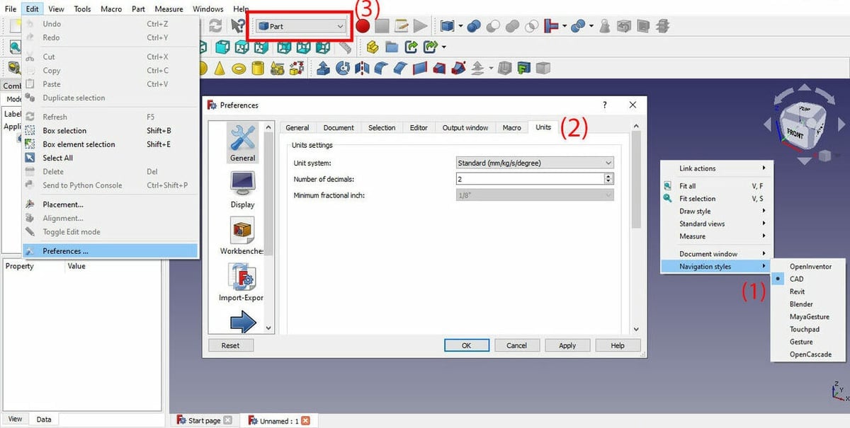
To set the navigation style, right-click anywhere on the workspace and go to “Navigation Style” (#1 in the image above). There, you’ll see many options. As we’ll be creating a model using CAD, the best option is to leave it as such.
Units
Units affect your project when you use dimensions and also when drawing, and they ultimately depend on the project you’re doing (or your personal preference).
To check the units, go to Edit, on the top menu, then “Preferences > General > Units” (2). In this case, we’ll use the metric system in mm, and if you’re modeling to 3D print, we recommend you do the same, as slicing programs usually work in the same system.
Workbenches
Finally, as we mentioned, FreeCAD is organized in workbenches. As we’ll be modeling, we’ll mostly be in the Part Design workbench, but we’ll also visit the Surface and the Part workbenches.
To switch workbenches, go to the workbench drop-down menu at the top of the toolbar (3). When you switch workbenches, you’ll see the tools in the toolbar change.
It’s also possible to customize the position of the tools by dragging and dropping them. We recommend moving them so that you can see all tools at the same time, as some will be stacked to the right of the screen and hidden.
Sketching a Base
We’ll start by modeling the bottom part of the chest. For our example, we’ll give you all the measurements, but if you’re creating something of your own that you plan to print, take care that the dimensions you set at this point will fit on your printer’s build plate.
To model the bottom of the chest, we’ll essentially model a hollow box without a lid (the lid comes later). To start, go to the “Part Design” workbench, where we find the sketching tools.
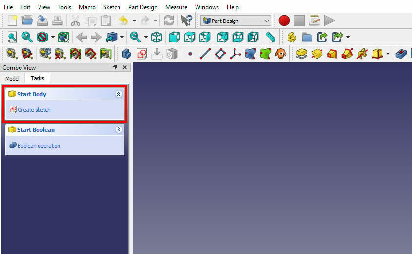
- Under the Combo View box to the left of the Viewport, go to the Tasks tab. You should see the option to “Start Body”.
- Click “Create sketch”, and FreeCAD will ask you to select a plane in which you want to design your model. Although this is a 3D model and you can rotate it around, it’s good practice to choose the plane according to how you’re going to design the part.
- As we’ll be drawing the bottom part of the chest, select the XY-plane, which is viewed from above. Then, press “OK”.
Sketching Tools
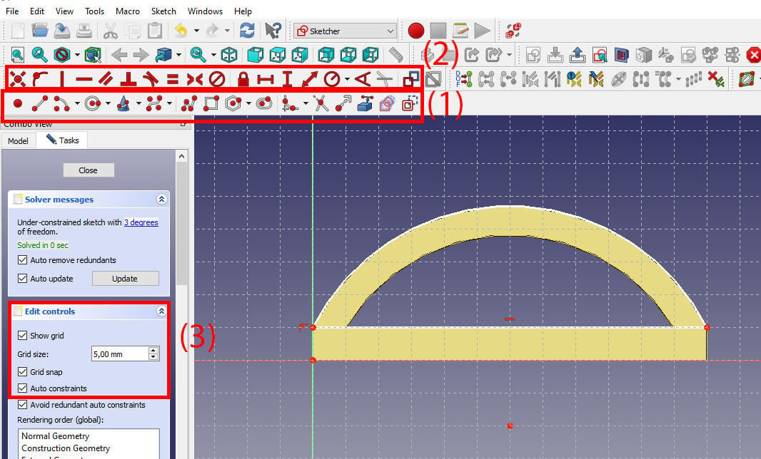
As FreeCAD is parametric modeling software, you sketch by using drawing tools (1) and constraint tools (2). To make sketching easier, you can enable the grid (3).
To show the grid, go to the Combo View in the Tasks tab. There, you’ll see a drop-down menu called “Edit Controls” where you can choose to show the grid, change its size, and activate grid snapping.
In this case, we’ll set the grid spacing to 5 mm. As we’ll be working with around 100 mm on each side, 5 mm is a good incremental space. If you’re designing a smaller model, you might prefer to choose smaller increments (e.g. a 10 x 10 mm model would work well with 1 mm spacing).
You can also choose to enable the “Grid snap” option, which will help you accurately place points at specific coordinates on the grid.
Drawing the Sketch
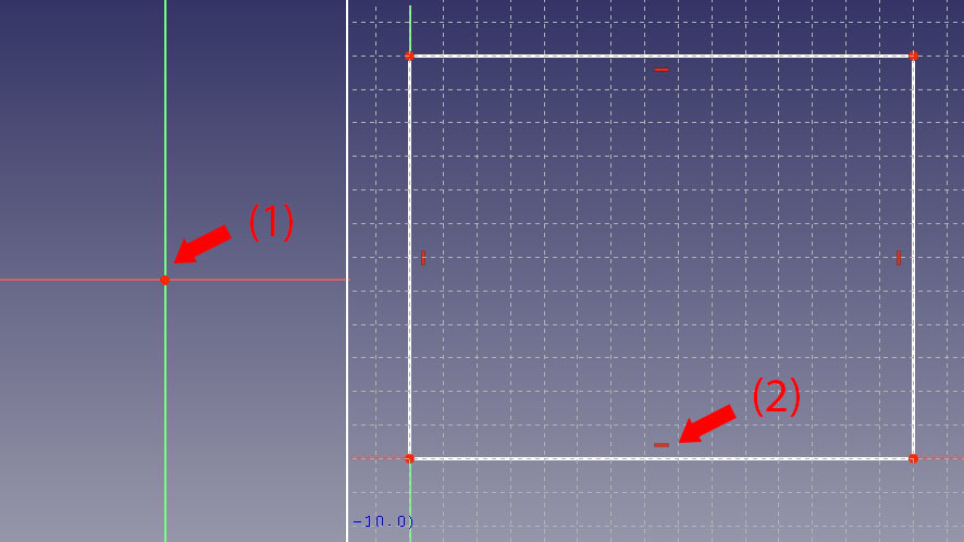
To sketch the chest bottom, we’ll start by drawing a base rectangle. The red dot in the center of the screen (1) is the origin point, so our coordinate system is in reference to this location. Move around in the Viewport by holding down the middle mouse button and dragging.
From the drawing toolbar, select the “Create rectangles” tool, then draw an 80 x 60 mm rectangle parting from the origin. You can see the coordinates as you move, which will help you draw.
When you’re done, you’ll see small straight red lines inside the rectangle edges (2). These are constraint lines, and they indicate the lines are horizontal and vertical.
The sketch is done for now, so we can head over to the Tasks tab and click “Close”.
Extruding a Base
The rectangle we now have is a 2D shape. Therefore, we need to give it some height so it becomes a 3D shape to form the base of our box.
- With the sketch closed, go to the Model tab in the Combo View panel where you’ll see there’s now a Sketch in the hierarchy tree.
- Select the sketch by clicking on it once. (Double-clicking it puts you back into sketch mode.)
- Switch over to the Tasks tab, where you’ll notice you now have several Sketch tools available.
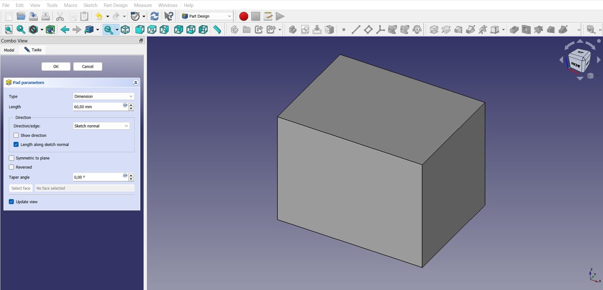
- For extruding this rectangle, click on the “Pad” tool. The rectangle sketch pops out into a 3D shape, which is by default 10 mm in length.
- Under the Pad parameters, set the length to 60 mm, then hit “OK”.
Creating the Hollow Box
Now that we’re working in 3D, we can convert our flat model into a hollow box shape. We’ll do that by creating a partial cavity in the model.
- Select the top face of the model.
- In the Tasks tab, select “Create sketch”. Now, the top face of our box is our sketching plane.
- Sketch another rectangle that will be the size of our interior. For a wall thickness of 5 mm, start the rectangle at (5.0, 5.0) and extend it to a size of 70 x 50 mm. Then, close the sketch.
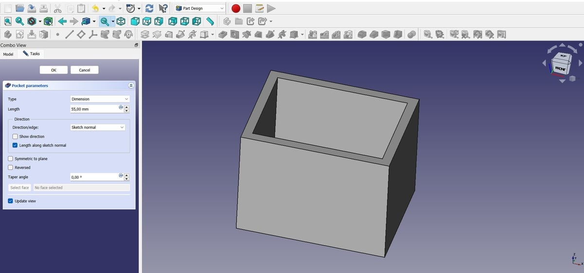
- With your new rectangle selected (the edges of the sketch appear green), head over to the Sketch tools in the Tasks tab and chose the “Pocket” tool. Again, you’ll notice the program has begun to create the pocket with a default length of 5 mm.
- Adjust the length value to 55 mm, giving our box a 5-mm thick floor.
If you’re designing your own model to 3D print, be careful about the wall thickness you choose at this stage. Walls that are too thin may not even be printable or could end up too brittle for practical use. Also, be aware that the height you extrude to shouldn’t exceed the build volume of your printer.
Adding a Lid Slot
Now, we need to make the slot where the cover will fit. We’ll need to remove some more material.
- Select the top face of our hollow box, and again, create a sketch.
- Draw a rectangle on the face along one of the long walls, leaving 5 mm at each end. Then, close the sketch.
- With the new rectangle selected, select “Pocket” in the Tasks tab again. You can adjust the length to your preference, but for this tutorial, we’ll keep it at the default 5 mm.
- Hit “OK”.
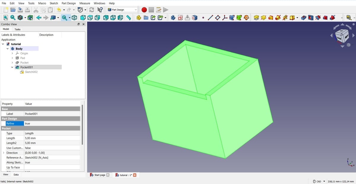
Now, let’s eliminate the extra lines generated by this new geometry:
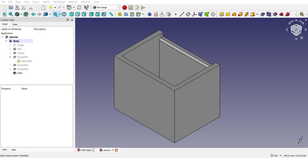
- Select the bottommost “Pocket” in the model tree.
- In the Properties window (just under the model tree), locate the Refine option under Part Design.
- Select “true” from the drop-down menu.
Adding Details
Now we’re going to add small holes on the inside of the chest so we can fit the cover. Similar to how we created the lid slot, we’ll now have to sketch on the inner side walls of our chest.
- Select one of these walls, then create a sketch. You’ll probably have to reposition the chest to find a good viewing angle.
- In the area on the side wall right above the top of the shorter wall, draw a circle using the Circle tool with a radius of 1.5 mm. (It might be helpful to first change the grid spacing to 0.5 mm.) Then, close the sketch.
- Extrude this shape into the wall using the Pocket tool. Set the length to 2 mm, then hit “OK.
- Repeat steps 1-3 on the other side of the chest.
The last detail we’re going to add is a fillet:
- Select the inner line edge on the top of the short wall.
- In the Tasks tab, select “Fillet”.
- Set a radius of 2 mm, then hit “OK”.
Creating the Cover
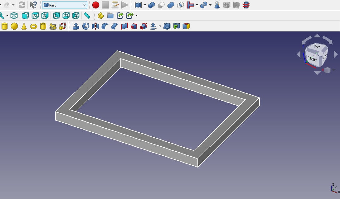
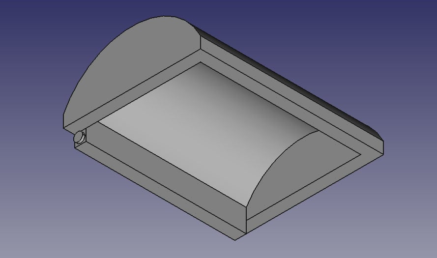
To build the cover, we’ll create a new part. Using what we’ve learned so far, create a hollow rectangle on the XY-plane, then use the Pad tool to extrude it 5 mm high.
The outside rectangle will be 80 x 60 mm, and the inside will be 70 x 50 mm (5 mm smaller in all directions) to match the chest. You can see the result in the image above.
Using Constraints
We’re now going to create a circle to give the cover a round shape. The steps described at this stage can be seen completed in the image above, so you know what you’re aiming for.
- With the original body selected in the model tree, create a new sketch on the YZ-plane.
- Use the Point tool to add a point at the top corners on both sides of the rectangle, as well as points 5 mm inward from both the corner points. We’ll use these to constrain and fix the circle to our object.
- With the midpoint 10 mm below the bottom of the solid (30 mm from each side), draw a circle.
- Complete and contain the circle by selecting one of the newly created corner points.
- Create a new circle with the same midpoint as the first one but constrain the radius to the inner points.
Trimming
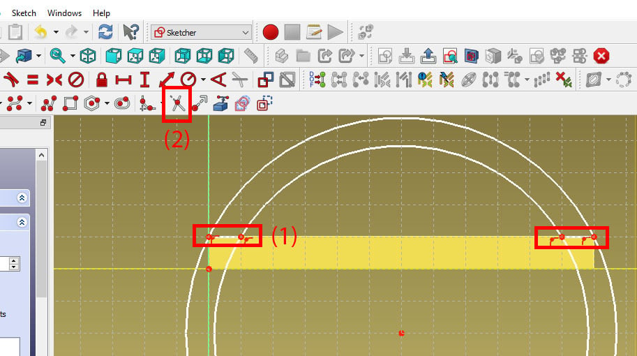
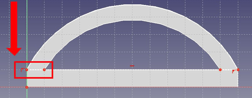
We only need a portion of the circle, so we’ll have to trim the unnecessary parts of it. To start, we’ll simply draw lines between our two points, which is where our circle needs to stop (1). This corresponds to the bottom and left-hand edges of the visible rectangle, as seen above.
To trim the rest of the circle we’ll use the Trim tool (2). Then, close the sketch.
Extruding the Cover
- Using the Pad tool, push out the arch until it reaches the other side of the model (80 mm). Then, hit “OK”.
- Eliminate excess lines by setting Refine to “true” in the Properties window of the Pad.
Now, we’ll have to create and fill in the side walls of the chest lid:
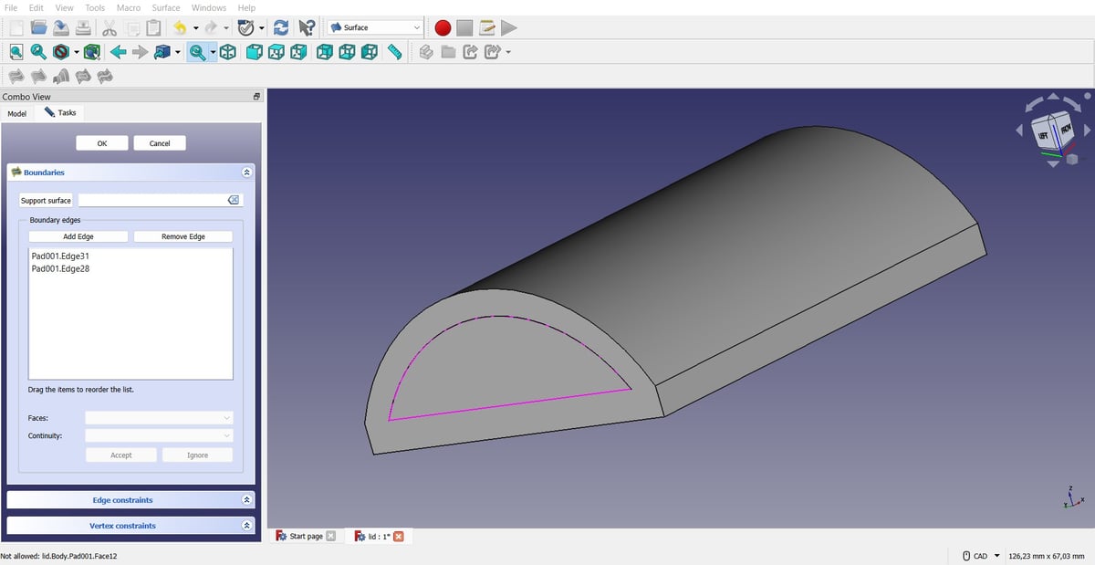
- Head over to the Surface workbench.
- In the header toolbar, locate and select the “Filling” tool.
- In the Tasks tab, select “Add Edge”, then select the two edges that make up the arc.
- Hit “OK”.
Finally, we’ll have to give thickness to the newly created side walls:
- Go to the Part workbench.
- Select the new surface, then click on the “Offset” tool in the header toolbar.
- Increase the offset to 5 mm (one side of the chest will need a -5 mm offset).
- Click the option to “Fill offset”, then hit “OK”.
Adding Details to the Cover
We now repeat the instructions of step 5 but for the cover. This will create the details that will allow our lid to snap on the box.
- Go back to the Part Design workbench.
- Select the bottom face of our lid, then create a sketch.
- Draw a rectangle on one of the long sides, leaving 5 mm on each end.
- Use the Pad tool to push out this shape by 3 mm.
- On one of the newly created side faces of the extrusion, create a sketch.
- Draw a circle with a radius of 1 mm, then use the Pad tool to give it a height of 1 mm.
- Repeat on the other side of the extrusion.
You’re all done!
3D Printing Considerations
At this stage, it’s a good moment to add some explanations about these dimensions and how they’re affected by the 3D printing process.
The cylinders attached to the cover are smaller both in diameter and length than the holes in the box. This accounts for the printer’s tolerance and to allow the parts to move. If the extruded and cut-away parts were designed to the same dimensions, they would be unlikely to snap together and would be difficult to move and use.
The results of your print ultimately depend on your slicer settings, but a common setting to use is a 0.2 mm layer height. With this setting, it will take five lines of filament to reach the length of 1 mm.
Any fewer lines of filament might not stand up to the wear of attaching and using the cover. On the other hand, the length is set to 1 mm because the tight fit means anything longer might break as you try to snap it into place.
Advice & Considerations
With our model done, let’s talk about some additional aspects about FreeCAD and how to 3D print a model.
When you save a project, it’s stored by default as a FreeCAD Document. If you want to save it for other uses, including 3D printing, you have to export the file. In this case, you also need to select which bodies within the file to export.
When exporting, you have many files options. Here’s a rundown of the most useful ones:
- OBJ and STL formats are useful if you want to 3D print or take into artistic modeling software to add detail.
- STEP and IGES formats are useful to keep information about specific software features used and are compatible with other modeling software, like SolidWorks and Fusion 360.
When you’re designing, it’s important to also plan for the manufacturing process your part will go through, meaning you have to take into account if certain geometries are actually possible to make.
Additionally, if you’re planning to 3D print your model, there are some special considerations to take. As we mentioned, things like wall thickness and your printer’s build volume are important to keep in mind if you’re designing a part to be a certain size.
For things like the snap-fit knobs used to assemble this box, you also have to take into account your printer’s tolerance either when modeling or when scaling it to print in order to make sure everything will fit together in reality.
License: The text of "FreeCAD Tutorial for 3D Printing: 8 Simple Steps" by All3DP is licensed under a Creative Commons Attribution 4.0 International License.