![Featured image of [Project] Six-Axis Robot Arm](https://i.all3dp.com/workers/images/fit=scale-down,w=1200,h=675,quality=79,gravity=0.5x0.5,format=auto/wp-content/uploads/2019/03/13160310/the-gripper-less-arm-demonstrating-its-stuff-john-lauer-youtube-190313.jpg)
[Project] Six-Axis Robot Arm

In this project, Jeff Kerr shows us how to make a six-axis robot arm that supports multi-axis coordinated motion. The arm is a scaled version of the industrial UR3 robot and includes several complex components.
Best for Long Weekends
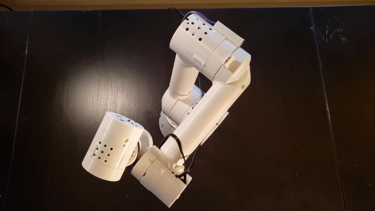
Need an extra hand for some fun, light assembly tasks around the house? Think no further than a scaled version of the UR3 robot with a gripper that conforms to the object at hand — great for picking up cups from the sink or holding a flashlight when there’s a blackout!
Enter this week’s a six-axis robot arm, coming to us from Jeff Kerr (Thingiverse user LoboCNC).
A word of warning: Building this arm is no simple task. It requires a set of actuators and a gripper, all of which are detailed designs that need to be printed and assembled separately. As such, you may have your entire weekend occupied if you want this baby to come alive before Monday.
Compared to most of our other Weekend Projects, this one is also a little pricier, costing somewhere between $300 and $400. That said, you needn’t worry about functionality, with both Jeff and YouTube user John Lauer having demonstrated its use.
Just make sure you follow the instructions closely and keep an eye out for changes or improvements!
Let’s get to work!
Actuators and Gripper
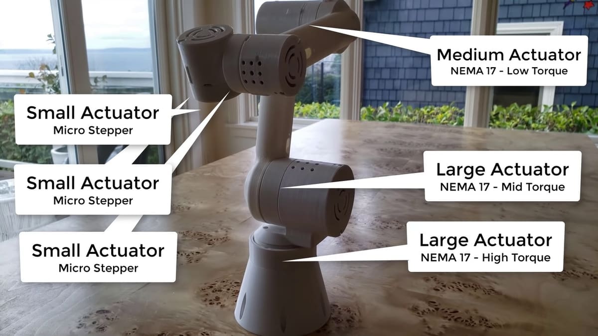
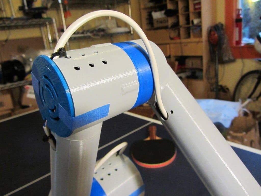
When all is said and done, you should end up with a robotic analog of a human arm (kinda), starting from the shoulder joint to the fingertips. In other words, there are three major joints — shoulder, elbow, and wrist — and the movement of these joints will be aided by actuators running code for acceleration and deceleration. The actuators, whose core components are microcontrollers and stepper motors, will be housed inside 3D printed shells.
Naturally, there’s also a gripper, which will work a bit like two human fingers. A motor aids in its movement.
Note: The actuators and gripper exist separately as standalone projects.
Actuators
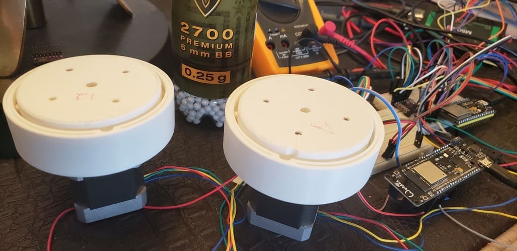
The actuators are a crucial part of this project, and Jeff has used a separate Thingiverse page to give all the details from printing to assembly.
In general, an actuator is a component that converts energy into motion. You can think of it as the opposite of a sensor, taking electrical signals as input and outputting movement in the physical world. Examples include electric valves, clamps, and motors.
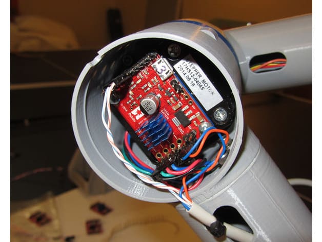
In the context of this project, the term “actuator” is used to describe not just the relevant stepper motor but also its surrounding assembly.
Actuator Specifics
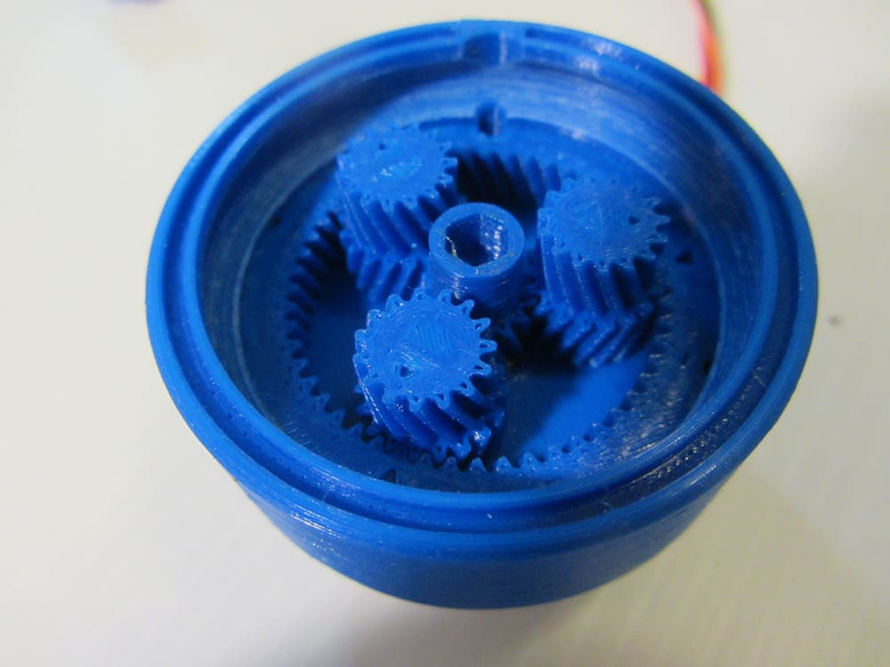
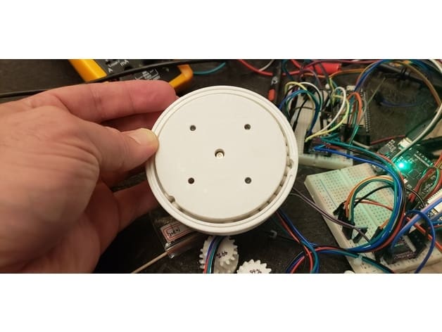
The actuators for this project consist of three planetary gearboxes, each of which use 38.4:1 compound planetary gearing.
What does that mean? Well, first you should know that a planetary gear system is one where the centers of one or more gears (the “planets”) revolve around the center of another gear (the “sun”). Secondly, the ratio refers to the difference in teeth of the connecting gears.
The three actuators use NEMA 17 stepper motors and vary in size according to the joints they control. John’s YouTube video shows how to assemble the actuators, which is particularly helpful since they are the most detailed part of the build.
Gripper
The robot arm is meant to be equipped with a conformal robot gripper. As with the actuators, Jeff includes all the relevant information (requirements, printing, and assembly) in a separate Thingiverse page.
The gripper’s pivoting fingertips should conform to most objects to provide a firmer grasp. Each “finger” is a rolling gear stuck between two racks, as Jeff preferred this over fixed pivots.
What You Need
For the requirements, we’ll assume you’re starting the project from scratch, meaning you need to make the actuators and the gripper.
Main Components:
- Planetary Gearbox for base rotation
- NEMA 17 Stepper Motor (59 N⋅cm) for the shoulder
- NEMA 17 Stepper Motor (40 N⋅cm) for the elbow
- 4 NEMA 17 Stepper Motor (13 N⋅cm) for the wrist and gripper
Please note that these are the recommended motors, but you are free to look purchase other equivalents.
- 7 Stepper motor controllers/FBAs
- Twisted Paired Cable (24 AWG)
- Female crimp pins
- 3/32″ heat shrink tubing (100 ft)
- 6-mm Airsoft BBs
- Du-Bro 362 6-32 Tap
- Du-Bro 361 4-40 Tap
- Double-sided mounting tape
Jeff used his own custom firmware to support the coordinated motion, and he has shared all the details — source code, docs, and programming — on Google Drive.
Screws and Nuts (approximate numbering):
- 30 6-32 x 3/8” zinc socket head machine screw
- 20 6-32 nuts
- 30 2-56 x 1/8″ button head socket cap screws
- 20 4-40 x 3/8″ hard alloy steel socket head cap screw
- 20 4-40 nuts
- 20 4-40 x 1/4″ flat head cap screw
Printing
According to Jeff, the structural parts of the arm should print easily without the need for support. He, personally, used a MakerGear M2 3D printer and PLA with the following settings:
- Resolution: 0.2 mm
- Infill: 25%
- Rafts: No
- Supports: No
John has a unique take on printing gears. He successfully printed the planetary gears — using AmazonBasics PLA — without the need for sanding. He used an Ender 3, and his settings were as follows:
- Resolution: 0.1 mm
- Rafts: Yes
- Nozzle temperature: 235 °C
- Bed temperature: 65 °C
He claims you’ll end up with a “mushy” gear bottom if you don’t use the raft, and it’s a pain to file the part. He also mentioned that he didn’t use Cura’s default “Sharpest Corner” but instead randomized the “Z seam alignment” to get the parts as smooth as possible.
Actuator and Arm Assembly
Actuators
Generally, the actuators will need some proper sanding and filing before you can break them in. According to John, a lubricant (like silicone grease lubricant) will go a long way in making sure the actuators run smoothly.
Refer to the Thingiverse page for the complete set of instructions.
Arm
Before you begin assembling and wiring the arm, lay out all the controllers and motors on a table and conduct some tests to confirm everything is working fine.
Again, Jeff has detailed the assembly process of the arm on Thingiverse.
You’ll have three main joints to worry about: the base cone joint, the shoulder joint, and the elbow joint. Once all the respective actuators are complete, you can worry about the wrists.
Wiring
Jeff admits that wiring can be a little hectic, mainly because the actuators don’t have a hole at the center like their UR3 counterparts. Therefore, you will need to determine how cables will run across each joint while still having enough slack for easy joint movement.
Jeff used a serial bus (V+, GND, TX, RX) with small controller boards that were distributed throughout the arm, and each motor had its own board. This is meant to reduce the number of wires running around.
A more detailed wiring process is available on Thingiverse.
Software and Testing
As mentioned earlier, Jeff has provided documentation on the modified firmware used for the T500 boards. The same directory contains a Windows test program and C++ source code for the test program.
Jeff acknowledges that the hardest part is getting his modified firmware flashed onto the board. You may have to contact the manufacturers (of your boards) to request if they can sell their board pre-flashed.
Otherwise, Microchip offers a video that might help you with reflashing the T500 boards, but you’ll still need to refer to Jeff’s firmware modification details to confirm how each pin should be connected.
The standard T500 board firmware can’t handle multi-axis movements that the arm requires, and this is what prompted Jeff to write his own. If you want the proper synchronization and coordinated motion, you’ll have no option but to program Jeff’s firmware into the controller boards. If you like, you can still go for the standard firmware, but you won’t get the best synchronization from all the joints.
John’s arm was a bit different:
- He used ESP32’s running the NodeMCU to create step signals, and he added buttons to start and stop the motors.
- He also added reverse directions to make breaking and testing easier. He used a DRV8825 chip (though he is considering a DRV8824 driver because the DRV8825 drivers were releasing excess current into the small motor) to drive the motors and the ChiliPeppr ESP32 for Lua workspace to write the code.
Feature image source: John Lauer / YouTube