Vref Calculator: How to Tune Your Stepper Driver

It's important to set Vref when changing or replacing drivers. Follow this guide and become your own Vref calculator!
Stepper drivers are small chips that, as implied by the name, are responsible for driving stepper motors, which can be found in 3D printers, laser cutters, and other CNC machines. Basically, they control the amount of current sent to the motors in different phases and pulses.
The A4988, the TMC2208, and the TMC2209 are well-known driver chips that usually come soldered to boards compatible with controllers like the Ramps 1.4 and its CNC shield. The actual boards are called “stepsticks”, and they vary from vendor to vendor while maintaining their form factor and pinout compatibility.
In this article, we’ll go through the steps required to calculate and adjust an important setting in stepper drivers, the VREF value. We’ll do this for the common A4988 driver as well as the advanced TMC2208 and TMC2209 drivers.
What Is Vref?
VREF stands for “voltage reference” and is measured in volts (V). In practical terms, it regulates the amount of electrical current delivered to the stepper motor, and this is essential for the proper and healthy functioning of both the drivers and motors.
Each stepper motor is specified to operate within an optimal electrical current range. Thus, an insufficient amount of current will cause the motor to lose steps during movement and therefore be less precise.
On the other hand, providing too much current to the motors will cause them to overheat, likely damaging them over extended periods of usage. The drivers themselves are also rated for a maximum current value, and running above this threshold will likely damage them very quickly.
This is why it’s so important to set VREF correctly, with the value depending on the particular driver chip and stepper motor used.
What You'll Need
Before jumping into the specifics of each stepper driver’s VREF calculation and adjustment, you’ll need to have a few details and tools available.
First, in order to calculate the right VREF value for a particular driver, you’ll need to know the rated current for the associated motors. This information is usually provided by the manufacturer, although for some motors, it can be a little tough to find.
The RepRap community keeps a detailed database on the most common NEMA 17 motors. You can navigate it by looking for the model number, which is usually displayed somewhere in the motor body. As an example, here we’ll be using a NEMA 17 42SHDC3025-24B, which according to the database, is rated for 0.9 A.
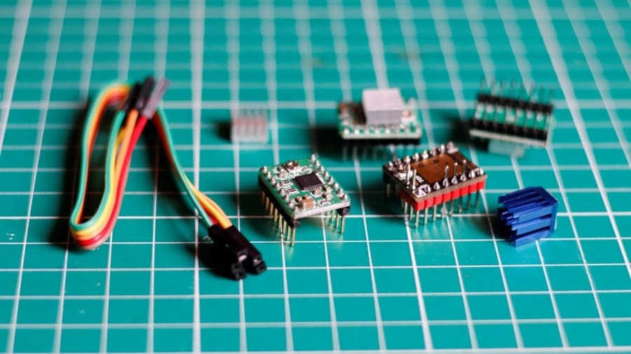
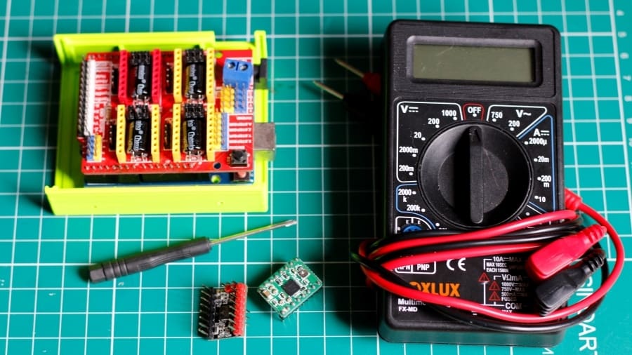
Adjusting the VREF value directly in the stepsticks will require some specific tools:
- Digital multimeter
- Controller board (3D printer or CNC) with a power supply
- Plastic- or ceramic-tipped screwdriver (highly recommended), usually 1.5 mm
A4988 Drivers
The A4988 is one of the most common chips used in drivers for desktop machines, including 3D printers. Developed by Allegro MicroSystems, they’re incredibly cheap and used in stepsticks from an array of vendors, with Pololu being the most recognized one.
How to Calculate VREF
VREF is calculated with a simple formula:
VREF = I x 8 x Rsense
Where I is the driver current to the motors and Rsense is the current sense resistor. While I is primarily defined by the motor’s rated current, Rsense is a fixed value that can be verified by checking the stepstick board.
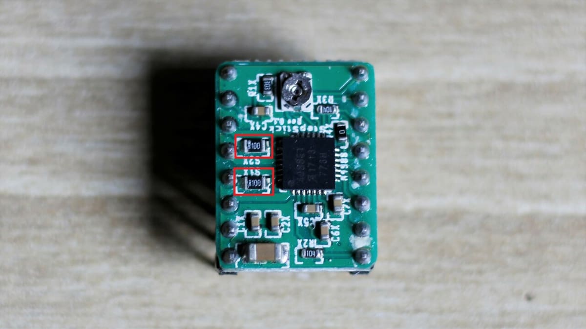
Sense resistors vary from vendor to vendor, ranging from 0.05 up to 0.2 Ω. Look for two equal resistors in the A4988, as shown in the image above. In this example, R100 is 100 mΩ, or 0.1 Ω.
Although the stepper motor we’ll use here is rated for 0.9 A, we should never set it to its maximum current capacity. It’s strongly recommended to reduce the amount of current to the motor by at least 10%, which in our case would translate to approximately 0.8 A.
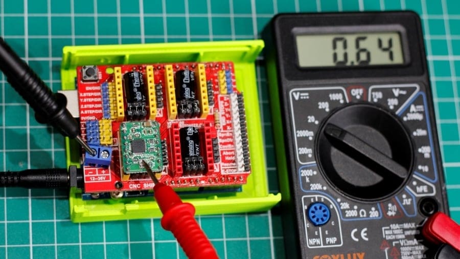
VREF = 0.81 x 8 x 0.1 = 0.64 V
How to Adjust VREF via Potentiometer
Now that we’ve calculated the VREF value, we just need to set it based on the driver. A4988 stepsticks come with small potentiometers that are used exclusively for this purpose.
To adjust VREF, follow these steps:
- Without turning the power on, plug the driver into the controller board of choice. Make sure to mount it correctly. Note that, for the Ramps 1.4 board, it must be attached to the Arduino Mega, too.
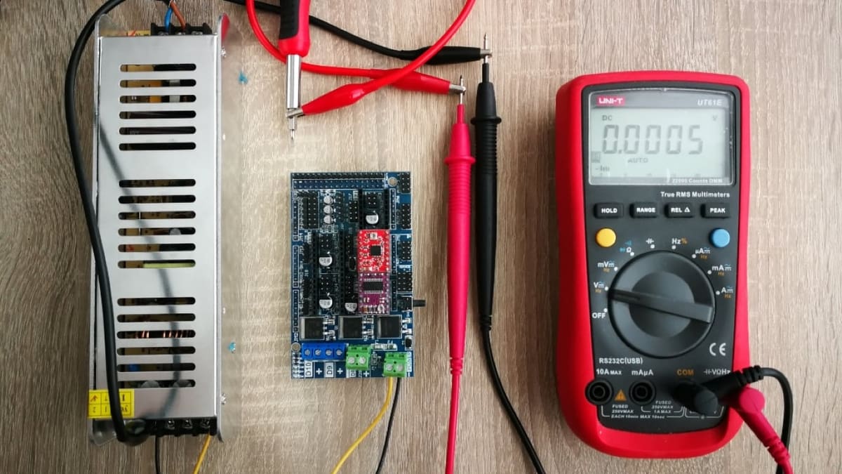
- Power up the board via VDD and GND, not via USB.
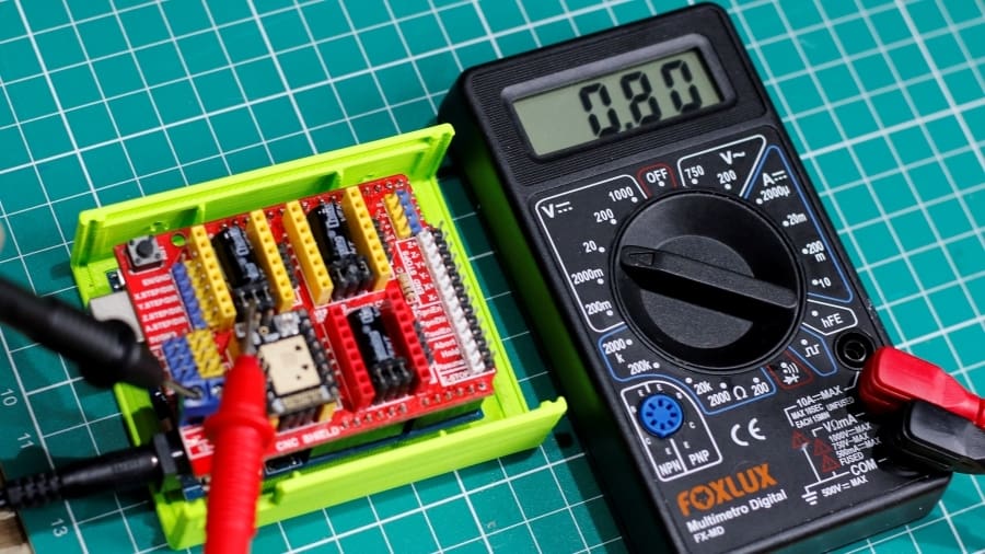
- Set the multimeter to DC voltage and to the proper scale (around 2 V).
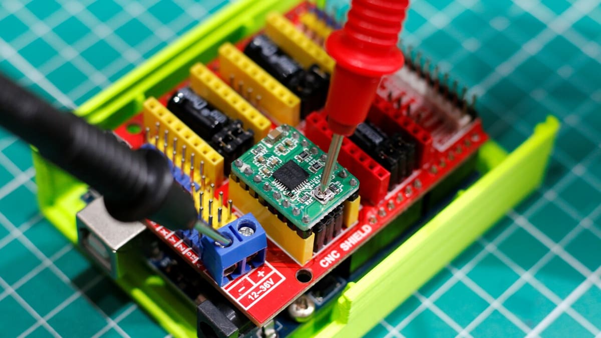
- Place the black probe on the controller board’s GND as shown in the image.
- Carefully place the red probe on the driver potentiometer to measure VREF as shown in the image. Pay special attention to the red probe – even touching other components could potentially short the driver or the controller board.
Now that we know the current VREF value, let’s use the screwdriver to adjust it to the value we calculated previously. This will involve iteratively adjusting and checking.
If you’re using a plastic or ceramic tip screwdriver, you should be able to turn the potentiometer with the power on without risking damage to the board. If not, we suggest powering off the controller board to safely adjust VREF, and then turning it back on to measure again.
The correct direction in which to turn the potentiometer knob differs from vendor to vendor. At first, try turning it slightly and measuring to check whether the voltage has increased or decreased.
Continue to adjust and measure VREF until an approximate value of the calculated VREF is reached. You’ll find that achieving the exact value is hard, but the closer you get, the better it will be.
And there you have it. Don’t forget to do this for all stepper drivers.
TMC2208 & 2209 Drivers

The TMC drivers are developed by Trinamic Motion Control. The TMC2208 and the TMC2209 are both very quiet and support up to 1/256 microstepping. As modern drivers, they can function in different operating modes: UART and standalone.
For UART mode, the stepper current can be set via firmware, whereas for standalone mode, this adjustment is manual and fairly similar to the A4988, as we’ll see.
How to Calculate VREF
The procedure to calculate VREF for both the TMC2208 and TMC2209 in standalone mode is the same. It might look a bit complicated at first, but stick with us.
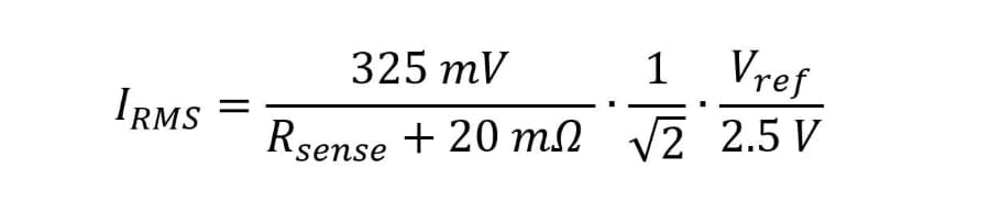
IRMS is the root mean square current and Rsense is the current sense resistor value.
Rsense for the stepstick can be visually checked. Similar to the A4988, there are two equal resistors but this time located at the bottom of the stepstick board. IRMS can be calculated by simply dividing the stepper current by the square root of 2.
To illustrate the process, let’s calculate VREF for a TMC2209 by BigTreeTech when paired with a 0.9-A stepper motor. Be aware that the TMC2208 has a maximum current output of 1.2 A, so be careful not to set above this value.
Rsense for this specific stepstick is R110, and for this formula, it should be provided as milliohms (110 mΩ). For the maximum current, we’ll once again use the value of 0.8 A (reduction by 10%).
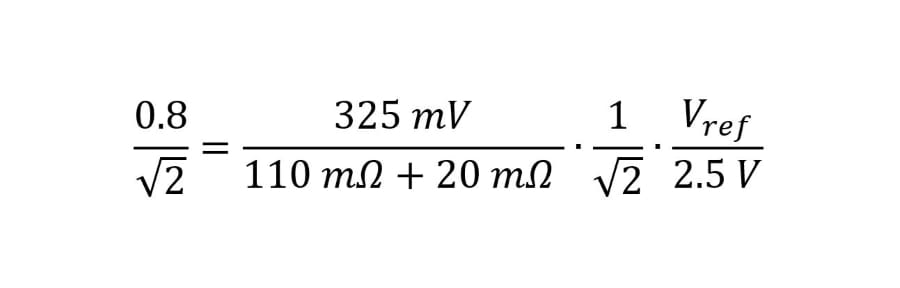
With some algebra, we find that VREF = 0.8 V. That wasn’t so hard, was it?
How to Adjust VREF via Potentiometer
To manually adjust VREF for the TMC2208 and TMC2209, we need to follow the same procedure as for the A4988, but the red probe must be placed in a different position (instead of on the potentiometer).
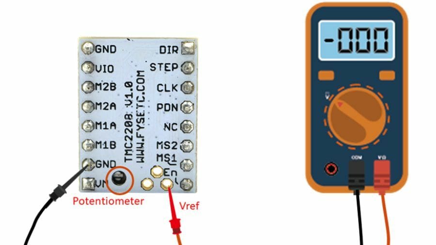
Usually, VREF is located as in the image above, but be sure to check the stepstick manufacturer’s documentation just to be on the safe side.
All the same recommendations and steps for adjusting VREF are valid here, especially when using a regular screwdriver instead of one with a plastic or ceramic tip.
And that should be it! Congratulations on correctly adjusting VREF for your stepper drivers. Now you can rest assured that both the drivers and the motors will function properly and within safe current margins.
Lead image source: Zero to Hero Engineering
License: The text of "Vref Calculator: How to Tune Your Stepper Driver" by All3DP is licensed under a Creative Commons Attribution 4.0 International License.