SolidWorks: Sheet Metal – Simply Explained

SolidWorks' sheet metal tool makes designing metal parts simpler. Follow along with our SolidWorks Sheet Metal tutorial!
SolidWorks is one of the most popular and complete 3D modeling software options. Once you’re an expert in the standard modeling features, it’s time to start learning some advanced toolsets, and Sheet Metal is a great place to start.
Sheet Metal in SolidWorks isn’t fundamentally different from normal modeling, so it isn’t a difficult stepping stone. It’s useful in many industries, from building small scale machinery like 3D printers to full industrial plants; having sheet metal in your arsenal of knowledge can bring you many advantages.
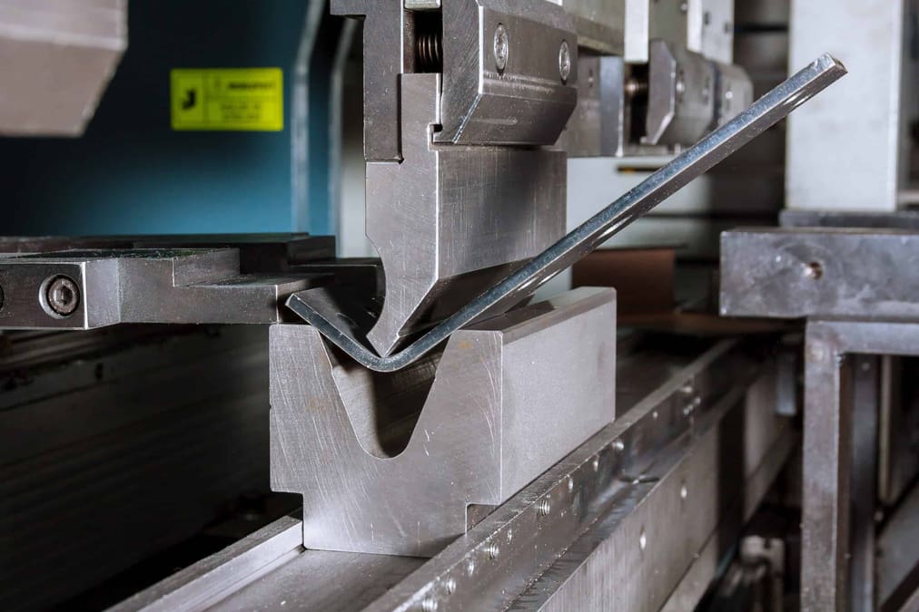
Sheet metal is, fundamentally, as the name indicates, a type of material: a sheet of metal. Parts manufactured with sheet metal can be bent, rolled, punctured, cut, welded, among others, and this is where the design process matters, as you have to account for these operations when designing.
In this article, we’ll follow a tutorial on how to create a pulley guard in Sheet Metal, but before we get to it, we’ll take a more in-depth look at what sheet metal design is.

Design for Manufacturing
At All3DP we know a lot about 3D printing, so it’s a good place to draw parallels from. When you design a model that you know will later be 3D printed, you have to take into account too-thin geometries that can’t be 3D printed and tolerances to ensure a good fit according to your printer’s resolution. This is called design for manufacturing (DFM), which means that, when designing, you take into account not only the application or final design intended, but also if its manufacture is possible.
Similarly, when you design for sheet metal, you have to think of the raw material needed, if the total dimensions exist in the market, the extra material needed to make the bends while keeping the final shape, the initial shape a sheet needs before it’s rolled, and more. SolidWorks’ Sheet Metal toolset helps you with all of this so you don’t have to calculate it by hand.
The Sheet Metal toolset is aimed to mimic the real-life process of creating the parts. There are two main areas of focus: modeling and drafting. As it’s designed for manufacture, you will design the model and someone else will likely manufacture it, unless you also own water-jetting and sheet bending machines. Therefore, an important part of the process is drafting appropriate blueprints so that the manufacturer can understand your design and what the final product must be.
Getting Started
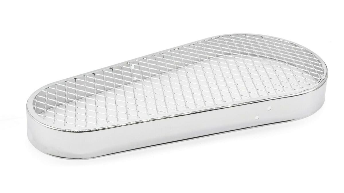
In this tutorial, we’ll design a pulley guard like the one shown in the image above. It’s a device used to isolate pulleys from the exterior environment, protecting them from debris. At the same time, it protects people from coming into contact with pulleys that are turning very fast, resulting in injuries. This design is simple and the purpose is to test some of SolidWorks’ capabilities – we won’t worry about pulley ratios or distances.
Since this is an advanced subject, we’ll assume you already understand basic SolidWorks concepts and therefore won’t go deep into explanations of aspects like creating a sketch or adding dimensions. If you feel like you need to brush up on your skills or want to get better acquainted with the program before jumping into the tutorial, there are a few courses you can look into.
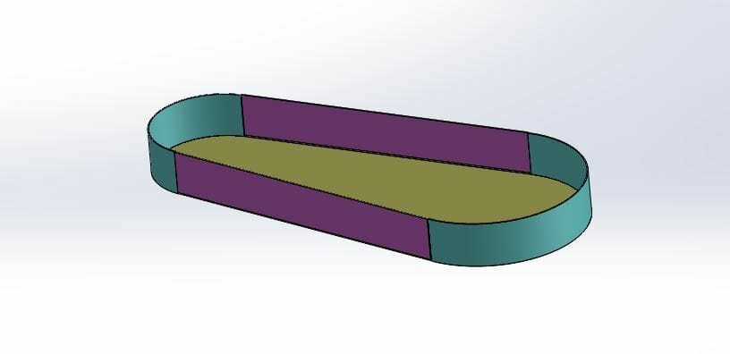
The image above shows the final result, and to have a clearer understanding, let’s establish the following terminology:
- We’ll call the yellow-green section the flat part.
- The purple parts are the flaps.
- The blue parts are the half-moons.
Additionally, the K-factor will constantly be popping up while working in SolidWorks, so let’s look at what it means now. According to The Fabricator, in sheet metal, “the K-factor is the ratio of the neutral axis to the material thickness.” This may seem confusing at first but worry not, SolidWorks uses a K-factor of 0.5 by default, and unless you’re planning on designing something very complicated (like a partial cone with non-concentric bases) you can leave it at that and get very exact results.
As a final note, in this tutorial we’ll use millimeters as the unit of measurement.
Setting Up Solidworks
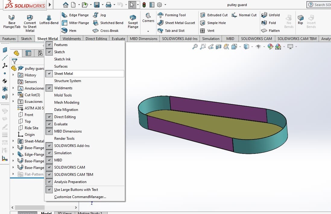
In the first part of the tutorial, we’ll be using the Part workspace of SolidWorks to create a model of a pulley guard. After opening a new part project, the first thing to do is check in the Command Manager if you can find the Sheet Metal tab. If you can’t, don’t worry, it just means it’s disabled.
To enable the Sheet Metal tab, right-click on any of the tab names of the Command Manager and all available toolsets will be listed. Just select the Sheet Metal toolset to add the tab to your display, and you’re all set to start.
Additionally, when working with Sheet Metal, the material matters because its properties can determine what can and can’t be done to a sheet of metal. With that in mind, we’ll set the material to ASTM A-36, as it’s a common commercial material for sheet metal.
Overview of Tools
Next, we’ll go over a few different tools that are worth knowing, as they’ll come into play in this tutorial or may be what you’re looking for your own project.
- Base Flange/Tab: Takes a sketch and converts that same geometry into a metal sheet with a given geometry.
- Convert to Sheet Metal: Takes an existing model made traditionally and converts it to Sheet Metal. This method is not recommended as it can lead to mistakes or may simply not work for the given geometry. Working with Sheet Metal from the start ensures your model can be manufactured.
- Edge Flange: Makes a flange from an existing edge. You don’t need a sketch, you only need to select the edge and indicate a distance, and in some cases, you can also indicate angle.
- Miter Flange: Similar to the Edge Flange tool, Miter Flange can be used for flanges that meet in a corner so SolidWorks takes the corner into account and does a nice cut there.
- Hem: Makes a curled flange, so it can essentially go from three bends to a full round flange.
- Bend: Allows you to take an existing sheet of metal and bend it twice to create an upwards or downwards bend, according to a sketch.
- Sketched Bend: Similar to the Bend tool, but it only does one bend.
- Flatten: Located to the outer right of the Sheet Metal part, Flatten is perhaps one of the most important tools as it allows you to see the raw material used to achieve all the bends and rolls.
Now that we know the basics, it’s time to start modeling!
Part #1: Modeling
Sketching the Flat Part
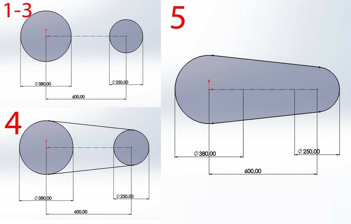
We’ll start with the simplest part to sketch: the flat part. This is essentially two circles with tangent lines and, as it doesn’t have to fit an existing pulley system, we can just input some arbitrary values. To create it:
- In the front plane, starting at the origin, draw a circle with a radius of 380 mm.
- Draw a construction line from the center of the circle to the right, with a length of 600 mm. This would be the distance between pulleys.
- At the end of the line, draw a second circle with a radius of 250 mm.
- Create tangent lines on the outer sides of the circles, connecting them.
- Use the trim tools to remove excess lines.
Creating a Sheet Metal Part
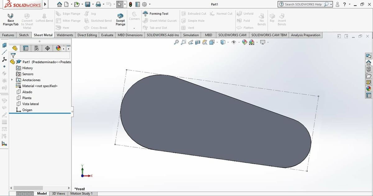
Usually, to create a volume from an existing sketch we would go to the Features tab, but in this case we’ll go to the Sheet Metal part. Here, we’ll use the Base Flange/Tab tool, as it’s the tool capable of extruding a sheet metal from a given sketch.
- Select the sketch.
- With the sketch selected, in the Sheet Metal Part, select the Base Flange/Tab tool.
- Here, we only need to input the sheet thickness. In this case, we’ll input 1.90 mm, which is also known as 14 gauge, and it’s a common sheet metal gauge.
This is a particular issue for Sheet Metal projects: You’ll want to input thicknesses that are available commercially, as it’s presumed that you’ll want to build whatever you model. The result will be a flat sheet metal part with the necessary measurements. And you may wonder, at this stage, why not just do it the traditional way, using the Features Tab?
Even now, when the sheet metal doesn’t have any bends and there’s nothing to flatten, if you click on the Flatten tool, a dotted line will appear around the metal sheet showing you the raw material you would need to manufacture this part. So even at this point, using the Sheet Metal tools gives you information for manufacturing you wouldn’t get treating this as an Extruded Boss/Base.
Creating the Flaps
Now, looking at the flat part, we can see that there are straight lines and curved lines. The half-moon will rest on those curves, and they have to be welded there, while the straight lines have the flaps, which can be obtained from bending a sheet of metal. First, we’ll create the flaps.
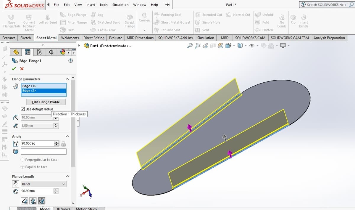
- Select the Edge Flange tool.
- It will ask you to choose the edges you want the flaps to start from. Select the straight edges and you’ll see right away that it’s created a bend from the existing sheet metal. You’ll also notice some extra options, like making the flange at an angle instead of normal to the existing surface. We’ll leave it normal this time.
- Set the Flange Length to 90 mm.
- Scrolling down there’s an additional option, called Flange Position. By default it should be in the first option, which is Material Inside. Because this eats away some of the existing material and that’s not what we want, we’ll change it to Bend Outside.
- You’ll notice that now the bend radius is too large, so scroll back up and change the bend radius to 19.0, the same as the thickness.
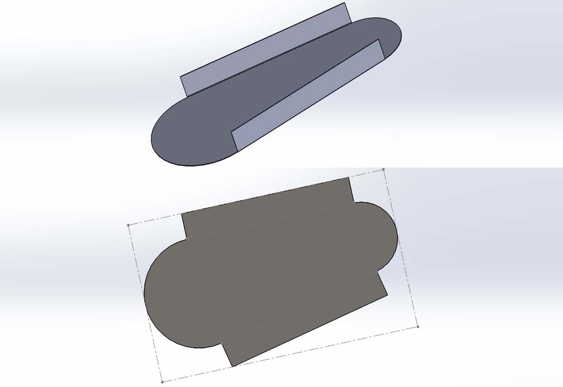
Once again, if you use the Flatten tool, you’ll see the raw material you need to manufacture your part. Notice that the bends have been flattened, so you know the total amount taking into account the radius, and it shows you an outer shape for the sheet you’ll need to cut.
At this stage, you can export the flattened result as a DXF or DWG to send to a water jetting or laser cutting service.
Creating the Half-Moons
The half-moons are parts that will be manufactured separately, as they have to undergo the rolling process and will be welded to the rest of the body. This is where SolidWorks is an especially useful tool. Even though they are separate bodies, you won’t need to create an assembly as you can use multi-bodies inside the part environment.
- To create the first half-moon, once again start a sketch in the front plane.
- Using the Convert Entities tool, convert one of the existing half circles.
- Exit the sketch.
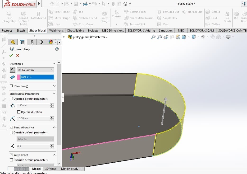
- That’s all as far as the sketch goes! Now once again go to Base Flange/Tab.
- When indicating the length of the flange, simply select “Up to Surface” and select the surface where the flaps end.
That’s all for creating the first half-moon. Now you just have to repeat the process to create the second one.
Notice how only one line without thickness or direction information was enough to create a Base Flange, as those properties can be input directly with the feature. Since you already have an existing sheet, the program uses that same thickness by default.
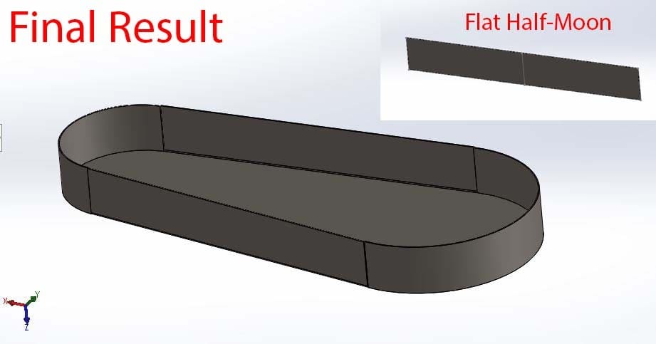
The final result can be seen above. If you select any of the two half-moons and select the Flatten tool, it will also show you the flattened raw material needed to create it.
With this, we’ve finished designing the part; now we’ll see how to create blueprints of it.
Part #2: Drafting
Separating Solids
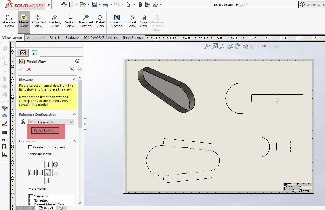
When you add a part to a SolidWorks drawing, all solids in it will be imported to the drawing, as shown in the isometric tools. But in this case, we have a multi-solid part and we need to show the solids separately. To do this:
- Once you’ve selected the model you want to import, the Model View context menu appears. Here, there’s a button that says “Select Bodies”, which opens the part so you can isolate which bodies you want to import.
- Doing this, separately bring each of the three solids into the drafting environment.
Showing the Sheet Metal Data
So, as we said before, we need information about bend angles, raw material size, rolling radius, and more, to be able to manufacture our part. How to find those?
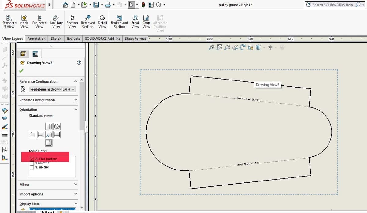
When you import the model, it will be in a standard view. The following process can only be done in a standard view, not in a projected view:
- Below the orientation options, you’ll see a box that says “More Views”, and one of those views says “Flat Pattern”. Select it.
- You’ll see your model has flattened and now it has annotations for bend angles, point of rolling, and other options. So, you can now add the required dimensions for the raw material.
With that, our tutorial is complete and you can graduate to modeling more functional metal parts, or just jump straight to your first spaceship!
License: The text of "SolidWorks: Sheet Metal – Simply Explained" by All3DP is licensed under a Creative Commons Attribution 4.0 International License.