Simply put, Onshape is a 100% cloud-based 3D computer-aided design (CAD) tool.
Developed by the founders of SolidWorks, the idea was to improve collaboration and simplify the deployment of the CAD tool. The platform focuses on collaboration and portability, and you can hear about Onshape directly from its creators.
In this tutorial, we’ll run through the steps from creating an account to drawing and exporting for the manufacture of the handle pictured at the head of this article. While this looks to be a simple shape that only scratches the surface of what the program is capable of, it uses all the tools that you need to create some very complex drawings.
We’ll also discuss creating assemblies for checking motion of mechanical parts, and lastly, we’ll touch on the usefulness of the Onshape mobile application.
Onto the first step, getting your Onshape account!
Step 1: Make an Account
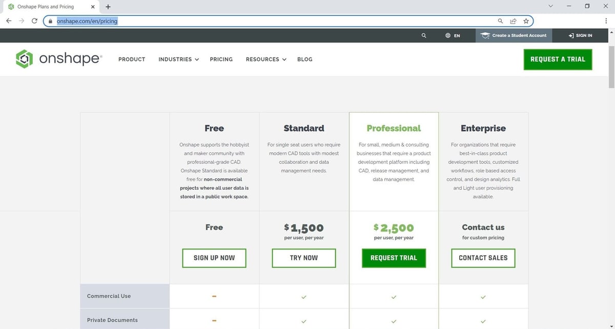
Getting Onshape is simple because it’s cloud-based, which means that you only need a web browser and decently fast internet connection. Simply go to the Onshape Plans and Pricing page and select your subscription level. For hobbyists, home users, and those just wanting to try it out with non-commercial designs, this might just about be the most full-featured “Free” version of a professional CAD tool available.
If you think that a free price tag will mean limited features or that you won’t get much out of it, don’t be deterred! The primary limitation (if you consider it such) is that all designs are publicly available for use by other Onshape users, and you can’t use the program for commercial purposes.
Additionally, the Simulation, PCB, and Render studios can’t be accessed without upgrading to a paid account. Some features around document and user control, such as Release Management (which is different from Version Management) and automatic part numbering are also unavailable. That said, most of the restricted features might not really be useful to a hobbyist or maker who isn’t going commercial anyway.
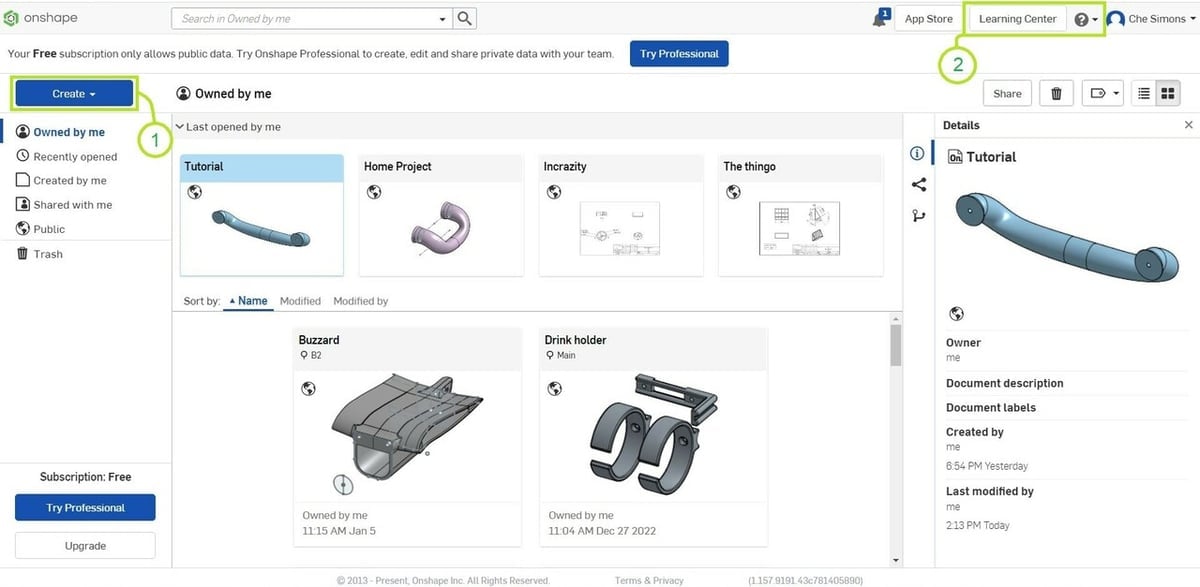
Once you create an account and log in, you’ll be greeted by the Document Page. Each document can hold an infinite number of Onshape’s subdocument types, and the main ones that we’re interested in today will be:
- Variable Studios, which are shared tables of easily editable dimensions that can be shared between parts (e.g. your “clearance fit” might be 0.2 mm, which could be then shared among all parts in that project).
- Part Studios, which is where the bulk of creating the parts takes place.
- Assemblies, which is where you can “virtually test fit” your parts together and see how they’ll move or work alongside each other.
Let’s jump into the tutorial.
Step 2: Create a Document
So you’ve got your account and you’re logged in, now it’s time to get some of that creativity onto the digital canvas! But how do you do that exactly? Well, first you’ll need a document to house everything.
To make a document, click on “Create” (1) and select “Document”. Remember, if you have the free version, all the design features are available to you, but your work is public and accessible to other Onshape users. Selecting “Document” brings up a form that allows you to name your new work and give it some labels (which should be meaningful to your design).
When your new document opens, it will have two tabs at the bottom, “Part Studio 1” and “Assembly 1”, with the former selected. This is good as it’s where you’ll want to start.
If you’re looking for other Onshape’s tutorial courses, you can click on the question mark (2) and select “Learning Center”, followed by “Self-Paced Learning”. Start with CAD Basics and work your way through them once you’ve finished this article.
But back to our design.
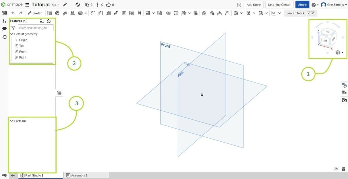
Across the top you’ll see various 3D tools – we’ll get to those shortly. To the top right, you’ll notice the View cube (1) which you can use to flick to pre-defined views. This is handy for quickly lining things up according to how you want to view them.
The “Features” list (2) will include all the actions you have taken on your 3D model, and you can arrange them to make it easier to find using folders.
Note that the actions happen in order from top to bottom. For example, if you add a chamfer on an extrusion and put it in a “Chamfers” folder that’s above the extrusion, the action will fail. This will become very useful and important as you gain more experience but isn’t a major issue for simple shapes like this tutorial.
Beneath the Features list, in “Parts” (3), you can find all the parts that you make within this part studio.
To get started, the first thing you need to do is sketch your idea. As mentioned, the next steps will walk through drawing a toybox handle for printing.
Step 3: Set Your Variables
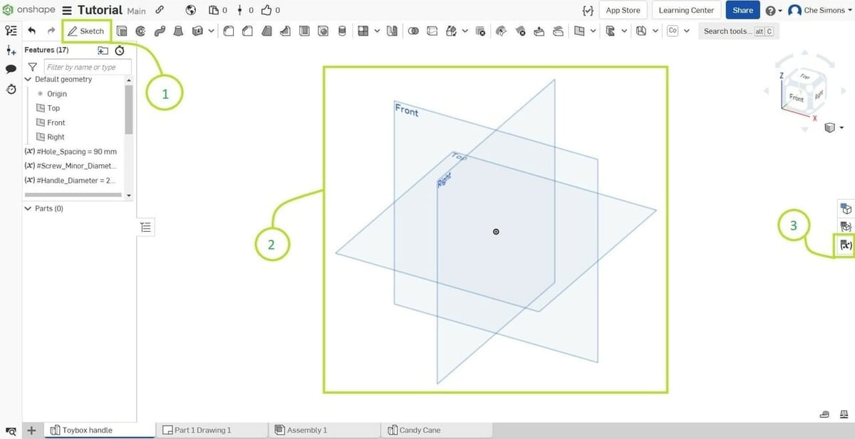
To create a sketch, select the “Sketch” tool (1). The program will ask you to define a sketch plane. This is simply done by clicking on any visible plane (2) (marked top, front, and right) either in the drawing space or in the “Features” list. For now, select the “Front” plane and use the View cube to quickly line up with the front plane for sketching.
Now, while you can just enter dimensions directly into a sketch, variables will make life a lot easier when you need to tweak your design later.
Just below the View cube on the side, you’ll notice three small boxes; we’ll be using “Variable table” (3). When you click on it, a blank table will appear on the right.
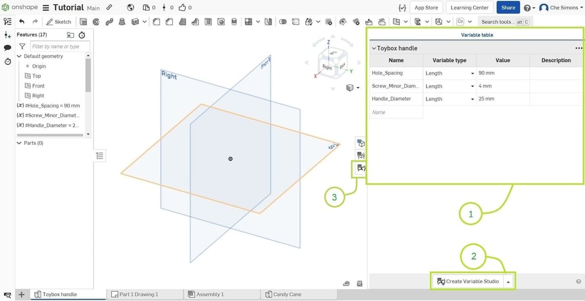
The entries in the Variable table (1) allow you to set variables that can be called upon multiple times or that have mathematical functions to determine relevant dimensions. This is handy for several reasons, but primarily because you won’t need to remember every instance you used a particular dimension when you want to make a change.
Add the following variables by typing the name, selecting the type, and entering the value. Note that variable names can’t have spaces!
- Hole_Spacing; Length; 90mm
- Screw_Minor_Diameter; Length; 4mm
- Handle_Diameter; Length; 25mm
If you decide to use a Variable Studio rather than the in-sketch table, click on “Create Variable Studio” (2) – you’ll now be able to add your variables in the same way, except that they’ll be available to all studios within the document. At the bottom of the Variable Studio is a button to copy the variables to all parts and assemblies.
Close the table for a better view of the workspace by clicking on the same box used to open the Variable Table (3). Now for the sketchy part!
Step 4: Create Your Sketch
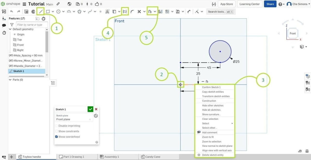
Draw a horizontal line originating from the origin by selecting the “Line” tool (1), clicking the origin (2), and then moving the mouse out sideways. Click where you want the line to end, and then hit Esc to exit the line tool.
Right-click the line and select “Construction” at the top of the context menu (3) – you’ll notice the line turns dotted. This indicates to Onshape that the line should be ignored for the purposes of enclosed sketch shapes, which will be important when we make our object 3D. You can also achieve this by selecting the Construction tool (4) from the toolbar.
Now locate the “Offset” tool (5). If you don’t recognize the different icons, simply hover over each icon and the corresponding name will appear. Select the “Offset” tool and click the line you just created. Drag the offset line upwards a little way. This should create a second line parallel to the first one at a distance you specify.
Click any blank spot in the workspace and a dimension box will become highlighted, allowing you to enter that distance we just mentioned. Type “Handle_Diameter” and hit Enter. Don’t worry if you accidentally click “Off”, you can modify it at any time by double-clicking the number.
Now make sure that Construction (1) and Offset (2) are unselected in the toolbar, and select the “Center point circle” tool (3). Hover the cursor over the outer point of your upper line for just a moment and then move the mouse upwards; a little yellow dotted line should appear. This constrains the movement to the vertical axis over that point. We want this but moving the mouse left or right too far will clear the constraint, so carefully move up a little further and left-click; this will start drawing a circle. Click the point you started on to complete the circle. The line we created with the offset tool should appear to be tangent to the bottom of your newly created circle.
Now to tidy up the sketch. Select the “Dimension” tool (4). Click your second (upper) line created using the Offset tool and then click again to place a dimension box. Enter “#Hole_Spacing/2”. You’ll notice that Onshape starts to suggest variables ahead of time, and you can select these from the list to speed things up. Now click the edge of your circle and click again to bring up the dimension box. Enter “#Handle_Diameter”.
Once that’s done, click the green tick (5) to complete the sketch. The box with the green tick allows you to change the sketch plane or rename it and can be moved around if it’s in your way.
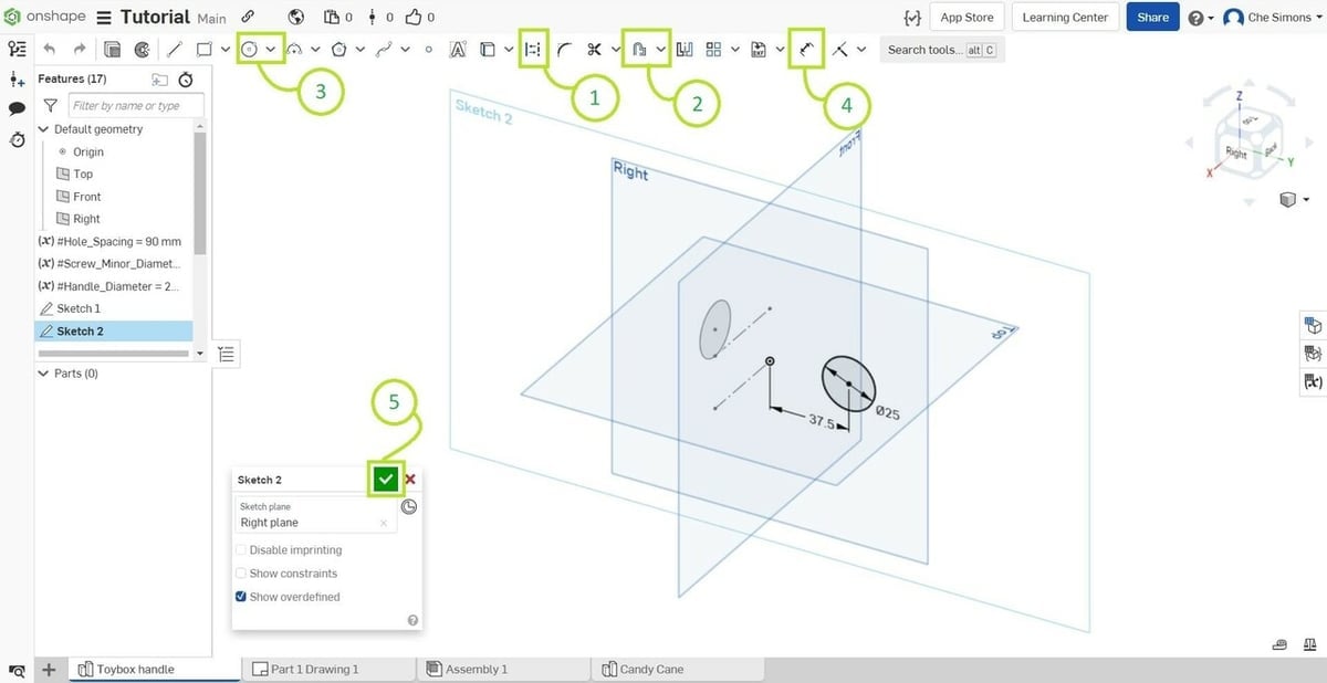
Now, try it on your own. We need a second sketch for this part to work. Create a sketch on the Right Plane, and draw a circle with the same diameter as in the first sketch, and position it centered one and a half handle diameters directly to the right of the origin (the dimension you enter should look like “1.5*#Handle_Diameter”).
Our next step will be to turn our basic sketch into a model.
Step 5: Extrusions & Revolutions
Okay, so we’ve got Sketch 1 and Sketch 2, but how do they translate into an object?
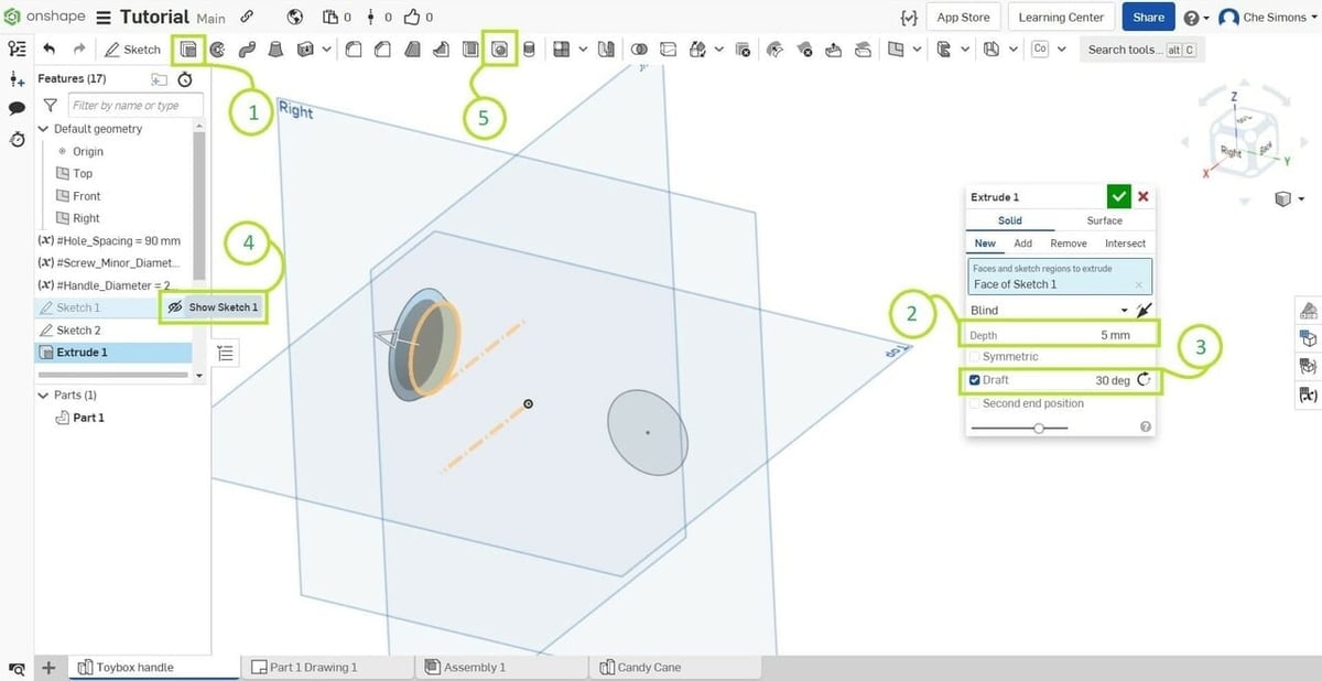
Well, there are a few ways to accomplish it. The first will be to extrude the base of the handle. Select your circle from Sketch 1 by clicking it on the Front Plane and either find the “Extrude” tool (1) or press “Shift + E”. Notice that an “Extrude 1” dialogue with several fields appears automatically. Unlike the sketch tools, a dialogue automatically appears for all 3D tools. You can also rename these features for ease of reference.
You’ll see a cylinder appear behind the circle. Make sure that the “Solid” tab is selected at the top of the Extrude dialogue box and enter “5 mm” into the “Depth” field (2). “Surface Extrude” creates a zero-thickness feature that can be used for more advanced modeling and is definitely a useful tool, but we’ll stick to the basics in this tutorial.
We also want the base to flare out slightly for better support, so tick “Draft” (3), which flares or compresses a surface relative to its direction of travel, and enter “30 deg” into the “Draft” field. Click the green tick box for Extrude 1.
We also need a hole for the screw to attach the handle. You’ll notice that Sketch 1 has hidden itself. You can access it by clicking on the eye (4), which allows you to hide and unhide sketches for better clarity. Unhide Sketch 1.
Select the “Hole” tool (5) to create the screw hole. Click the center point of the circle on Sketch 1 and in the hole diameter dimension type “#Screw_Minor_Diameter”. Don’t worry about the other two dimensions for now. Select the green tick.
Now we need to build the rest of the handle.
Select the circle from Sketch 2 on the right plane and follow the same steps as for “Extrude 1” to extrude it, but this time set the depth to “#Handle_Diameter/2” and don’t add a draft (leave the box unchecked).
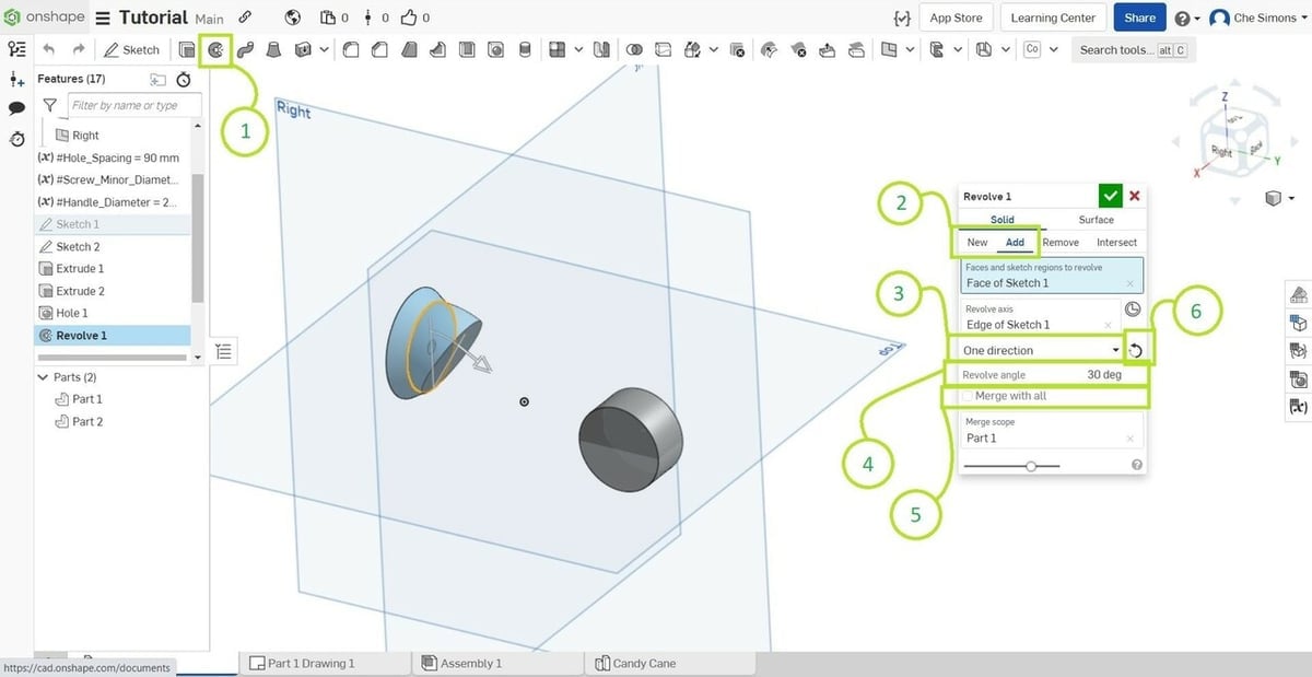
Next, select the “Revolve” tool (1) and check that you’re making a solid, not a surface, in the same way as for extruding earlier. Click the circle from Sketch 1 in the front plane (be careful not to select Part 1, with the hole in it). Next, select the upper line in Sketch 1 as the revolve axis. Now change from “New” to “Add” (2) and from “Full” to “One Direction” (3), then enter “30 deg” into the “Revolve angle” field (4). Check “Merge with all” (5) to make sure that the part builds on the base.
You may need to reverse the revolve direction, which can be accomplished by clicking the arrow to the top right of the “Revolve angle” field (6). Select the green tick once it looks right to you.
Step 6: Lofting
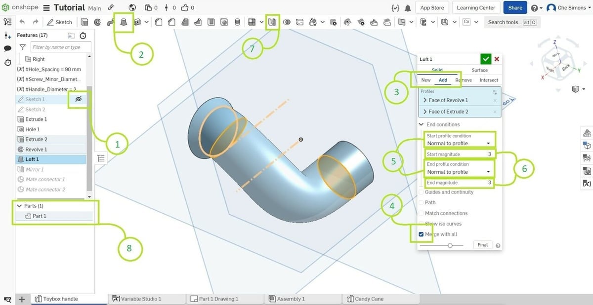
Our last trick will be to join the two parts using a tool called “Loft”. Hide both sketches (1) and select the “Loft” tool (2).
Change from “New” to “Add” (3) and select “Merge with all” (4). Now click the front face of your revolve and the face of your second extrude closest to the base of the handle. They will become joined by a gooey-looking strut. To make this look nicer and more like a handle, change both the Start and End profile conditions (5) to “Normal to profile”. This makes the lofted object extend outwards perpendicular (normal) to the selected feature, whereas leaving “Tangent” selected will cause the loft to extend along the same plane as the selected feature.
If it still doesn’t look quite right (as expected), play around with the Start and End magnitudes (6). These change how far the object “throws” out from the features you’ve selected. A small magnitude will pretty much head straight from the start profile to the end profile, whereas a large magnitude will go out quite a way and then curve back on itself. It’s easiest to play around with the number to see the effect.
In this instance, a magnitude greater than 5 will be unsolvable for Onshape (the reasons are complicated but with experience they become obvious). We opted for a magnitude of 3 for both the start and end. Once you’re happy, select the green tick box.
But wait, that’s only half a handle! The good news is, a whole and perfectly symmetrical handle is but one more feature away. Select the “Mirror” tool (7), change to “Add”, and select “Merge with all”. Select “Part 1” from your Parts list (8), and the face of your second extrude that remains exposed. After hitting the green tick, you will have modeled a toybox handle!
So, what can we do with such a model?
Step 7: Create an Assembly
Okay, so this one might seem a bit silly. We’re going to connect two handles together and then animate one of them to spin around like it’s loose on the screw. This is merely to show you how the assembly feature works.
It’s a really useful tool that lets you visualize how designs that have moving parts might work. It has some limitations, such as all the parts have no mass or inertia, given that it’s not a simulation (that is one of the few restrictions on the free version). But it’s very useful for visualizing clearances or how complex mechanisms like multiple pin slots might interact with each other.
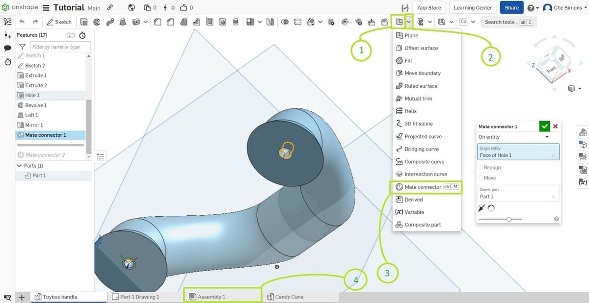
For our purposes, we’ll need to add mate connectors, for which you’ll stay in the Part Studio for now. In the toolbar, towards the right-hand side, next to “Plane” (1), you’ll find the drop-down arrow (2). Click on it and select the “Mate connectors” (3). Alternatively, just press “Ctrl + M”. Zoom right in on the screw holes and place your mate connector in the center of the empty space in the hole. Do that for both sides of the handle.
You’ll notice that your document automatically created the “Assembly 1” tab (4). Click on it and you’ll notice that the toolbar has changed significantly.
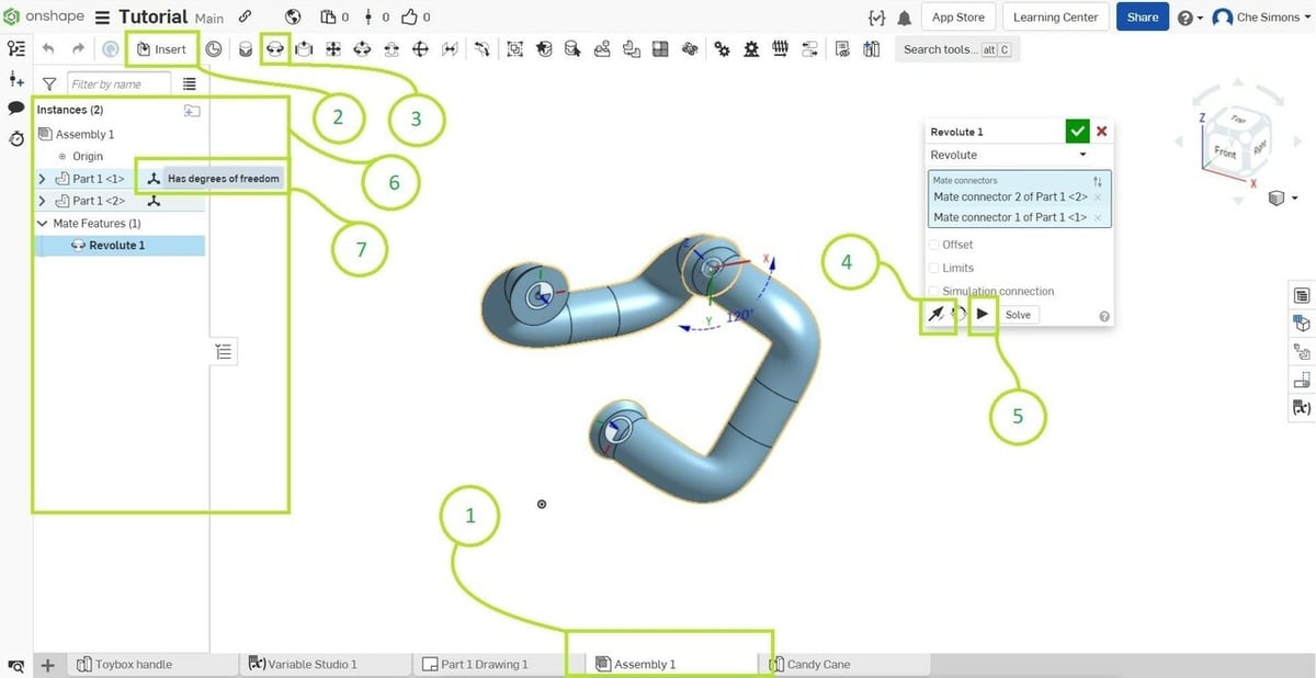
In “Assembly 1” (1), because you’ll need some parts, click the “Insert” tool (2). A dialogue will appear with your toybox handle visible. Select your Toybox Handle and place it in the space. The dialogue will remain visible, and we need another object so select and place another copy of your handle. Once placed, click the green tick.
Now, find the “Revolute Mate” tool (3). Select a mate connector on one handle, and the opposite one on the other handle. The parts are now clipped through each other, which isn’t right. Near the bottom of the Revolute 1 dialogue box, click on the set of arrows that are facing opposite directions (4). You should now have an assembly of what looks like a continuous pipe. For a bit of fun, click the play button (5) to make one handle spin around…
A more useful feature is in the “Instances” menu (6). Next to each part, there’s a little three-arrow icon. If you hover over it, it will say “Has degrees of freedom” (7). Click this to bring up an orientation widget for your handle. You can now rotate the handle and you can see that the other handle remains joined as if on a pin. It doesn’t take a huge amount of imagination to see how this could come in handy when designing something that moves, like a cam system or a hatch.
But what else can you do with these drawings?
Step 8: Materialize Your Design
Well, you’re reading a 3D printing web magazine, so you might assume that you can 3D print your designs. You’d be absolutely right!
Exporting a design is as simple as can be. Return to your Part Studio and right click your part (Part 1 if you haven’t renamed it). Select “Export” from the context menu to bring up a dialogue box.
Choose the format (STL, OBJ, and 3MF are the usual, but other formats are available) and check the parameters. On a side note, older versions of Simplify3D, FlashPrint, and a few others seem to struggle unless the STL format is “Text”, but a Text-based STL seems to work fine with nearly all other slicers.
Hit the blue “Export” button and your file will download.
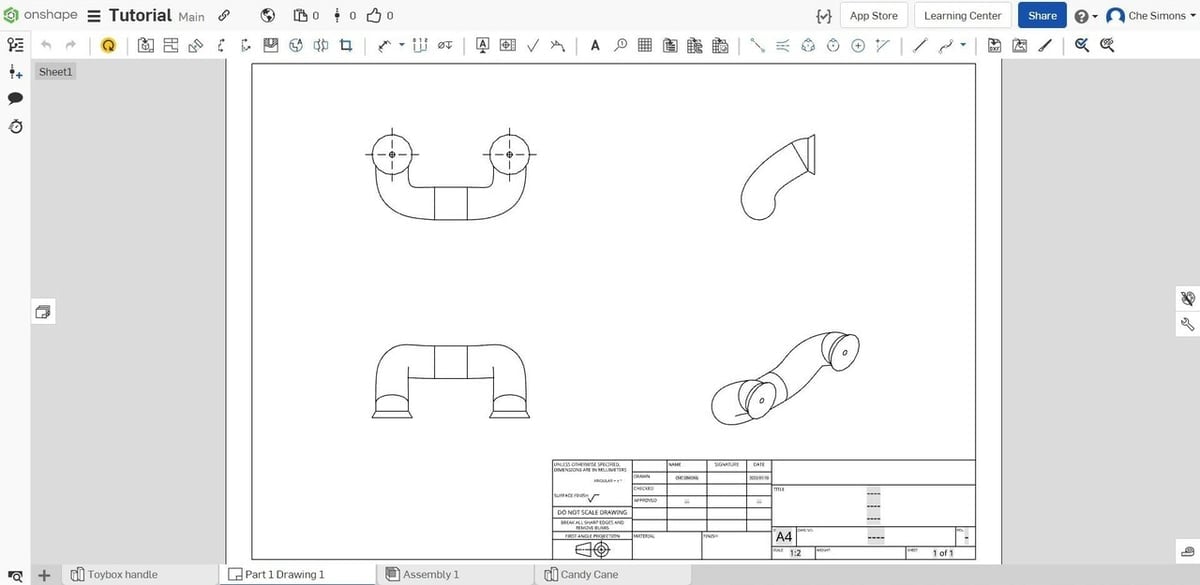
If you want to send your part to a machinist, or perhaps a laser cutter, again right click the part but this time select “Create Drawing of Part1…” from the context menu. Doing so will open a dialogue where you can select a template, and if you want any views pre-populated. Hitting “OK” will open the drawing in a new tab within your workspace. This can be exported in a variety of formats, including DXF, PDF, SVG, JPEG, and several others, by right-clicking on the tab and selecting your desired format.
If you’re sending your design to a fabricator, then a multi-view or set of different view drawings would be recommended (discuss your fabricator’s requirements with them to get it right; an experienced fabricator will also be able to tell you what design features may work well or may fail).
Another option to really broaden your available material options would be to engage a 3D printing service such as Craftcloud by All3DP. Simply export your model for 3D printing and upload it for an instant quote!
Step 9: Get Mobile & Share
Remember how we said that the Onshape developers were focused on collaboration and flexibility?
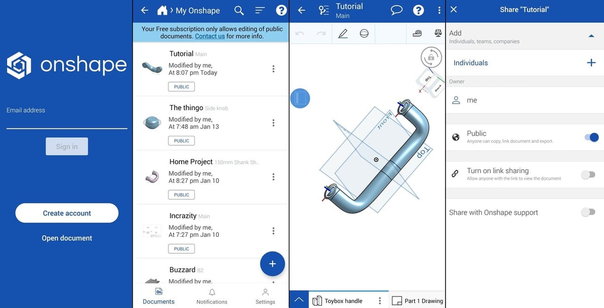
Well, to really see the power of Onshape’s cloud-based platform, you could start by using the mobile app, available for Android and Apple. The apps let you log in to your Onshape account from your mobile device, which makes it very easy to upload reference photos. They also carry all the features of the platform in a mobile-friendly layout so that you can edit your designs wherever you are.
This is very useful for tweaking variables and features if you have to measure something away from your computer.
When it comes to sharing, the Onshape app accesses your device’s contacts, a handy feature that isn’t available in the browser version. In addition to the documents being publicly available by default (for the free version), you can add specific people, teams, and companies to share them with, as well as enable link sharing.
Of course, you can share your files from the desktop program too. If you click the Onshape logo at the top left of your screen, you’ll return to the Documents menu. On the left, you’ll see a list of filters. Selecting “Public” shows you all the public documents generated by the Onshape community. There are a lot of generically named documents in the public files, so the best way to share a document with your fellow designers is to (first return to “Owned by me”) right-click the document you wish to share and select “Share”. This brings up a dialogue box where you can enter e-mail addresses. Alternatively, you can select “Link Sharing” to allow anyone with the link to view the document.
While you can get Onshape to work in your mobile browser, there are good reasons to use the app instead when on mobile!
License: The text of "Onshape Tutorial: How to Use Onshape in 9 Easy Steps" by All3DP is licensed under a Creative Commons Attribution 4.0 International License.