Klipper: Z Offset Calibration – Simply Explained

In Klipper, Z offset calibration is a basic but important procedure. Read on to learn all about how it's done!
The first layer of a 3D print is crucial to get correct if we want to be successful in our 3D printing endeavor. To achieve this, we need to have a consistent and accurate distance between the extruder nozzle and the print bed. To make things a little more complicated, that distance must remain correct, even if we make changes to the print bed. This is where the Z offset comes in.
In this article, we’ll explain what Z offset is and why it’s important. We’ll also discuss when you should calibrate the Z offset and how to do it in Klipper, a popular open-source alternative to Marlin firmware. Klipper is 3D printer firmware that’s designed to process complex operations on the more powerful Raspberry Pi. The latter connects to the 3D printer control board and only sends simple movement commands, thus lifting the performance bottleneck caused by less powerful control boards.
Regardless of the firmware you use, it may be necessary to calibrate your printer’s Z offset, especially if you’ve made any upgrades, modifications, or other physical changes to your printer. Read on to learn more about it!

What Is It?
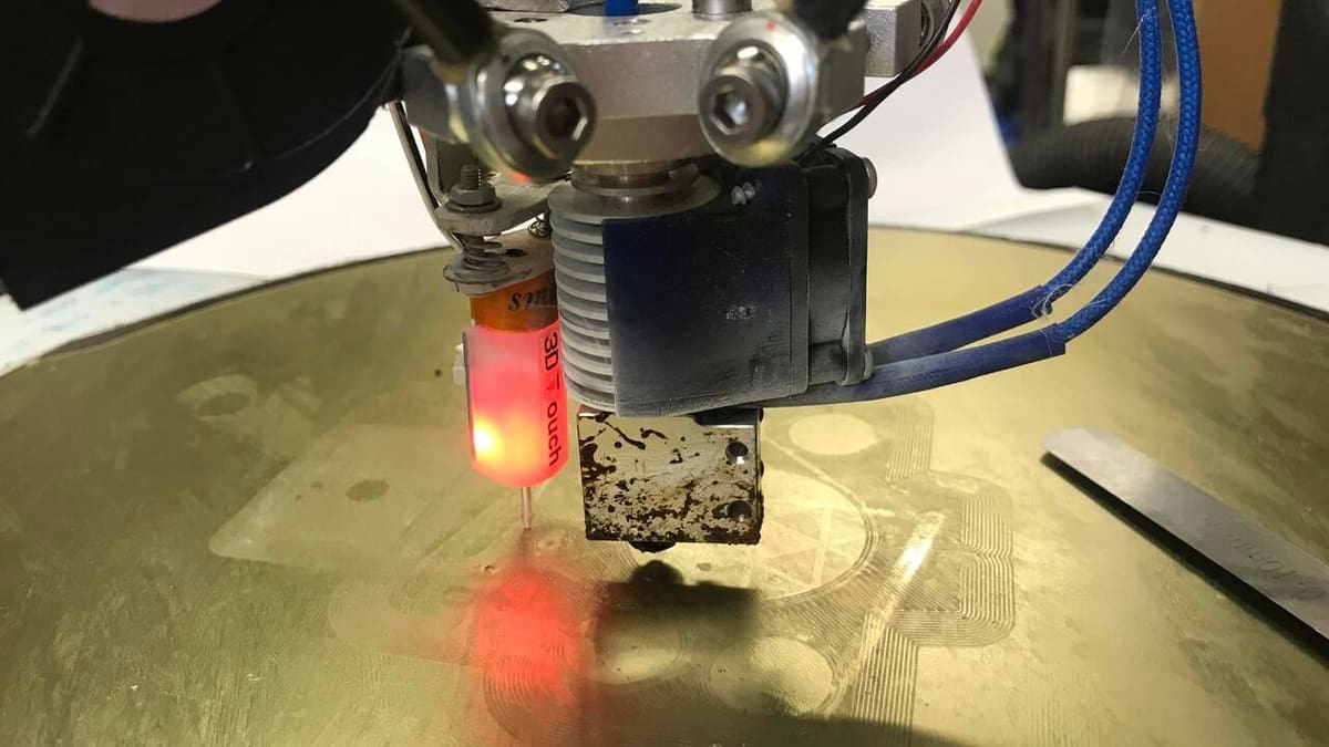
The short answer is, it’s the height difference between the bed probe activation point and the actual nozzle height in relation to the print bed. Therfore, the Z offset depends on two things: the probe and the nozzle. If we influence or change either one, the Z offset is most likely incorrect.
There’s a lot of detail in the definition above, so let’s break it down. In addition to a bed probe, we’ll need to understand what the bed probe activation point is and how to correctly measure the height difference.
When it comes to the probe, it doesn’t matter if it’s an automatic probe or a manually deployed one because the nozzle will always be a certain distance away from the bed if we don’t want to damage our printer bed. Automatic bed probing is simply more convenient and faster compared to manually deployed probes.
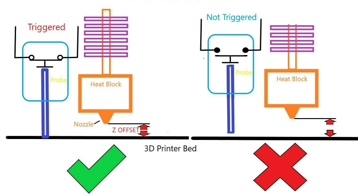
The activation point of a probe is simply the point at which it switches from one state to another, thus indicating contact with the build plate.
It follows that the height difference between nozzle and probe doesn’t matter as long as it remains the same and the probe triggers before the nozzle can touch the build plate. But this is where some probes can come undone.
Why Calibrate?
In an ideal world, our printers never move, the build plate remains unharmed, and the ambient temperatures remain constant. Nice, isn’t it? Let’s snap out of this dream and look at what really happens.
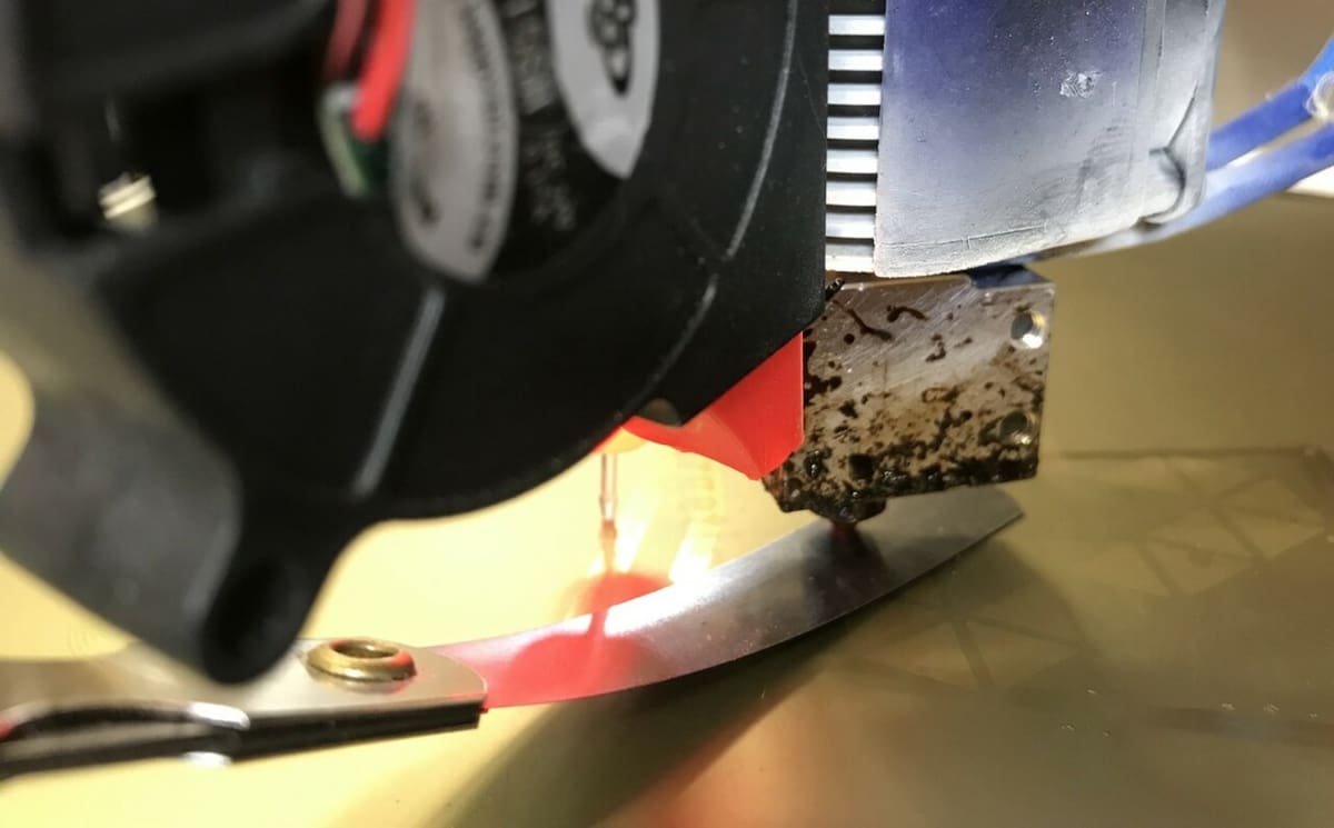
With space often at a premium and with some printers being rather large, most makers don’t keep their machines in a nice temperate office but rather in a basement or a workshop garage. They can get moved around, sometimes accidentally knocked, and let’s not even start with pets.
As you can see, the temperature conditions aren’t necessarily ideal, and the abuse your 3D printer takes may distort its frame. All of these factors impact the Z offset, and some are easier to resolve than others.
Temperature Bias
The ambient temperature where your 3D printer is located affects the machine in several ways. The entire printer assembly is subject to thermal expansion and contraction, which – depending on the material – can influence the calibration of the printer.
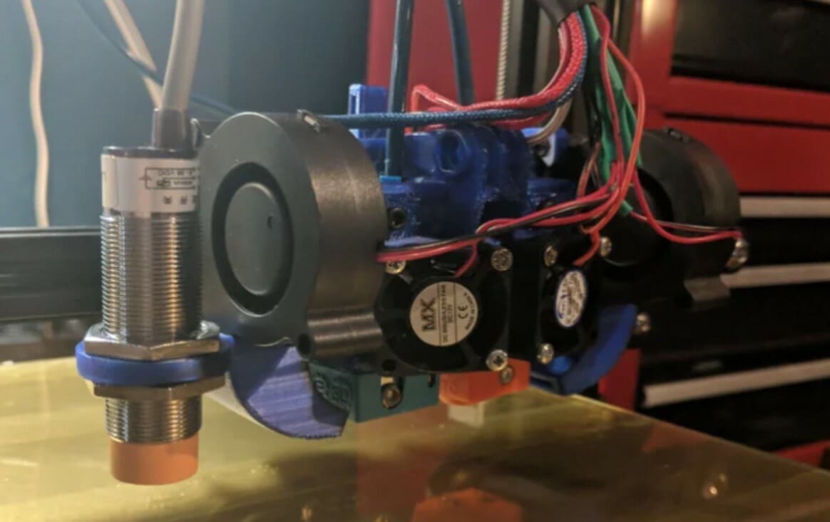
More importantly, capacitive probes are directly affected by temperature: The trigger point changes slightly as a function of temperature – which is called “temperature bias”. If the trigger point changes, so does the height of the nozzle above the print bed at that time. And remember, we want this to stay constant at all times!
Fortunately, temperature bias is the easiest to deal with. If a capacitive probe is used, one needs to keep in mind that the trigger point is dependent on temperature. The Klipper documentation recommends keeping temperature conditions constant, but that’s difficult in winter while working in a garage.
The remedy here is to create a temperature-dependent calibration table and adjust the 3D printer accordingly. This means running the calibration procedure for a range of ambient temperatures or simply calibrating the probe on the day.
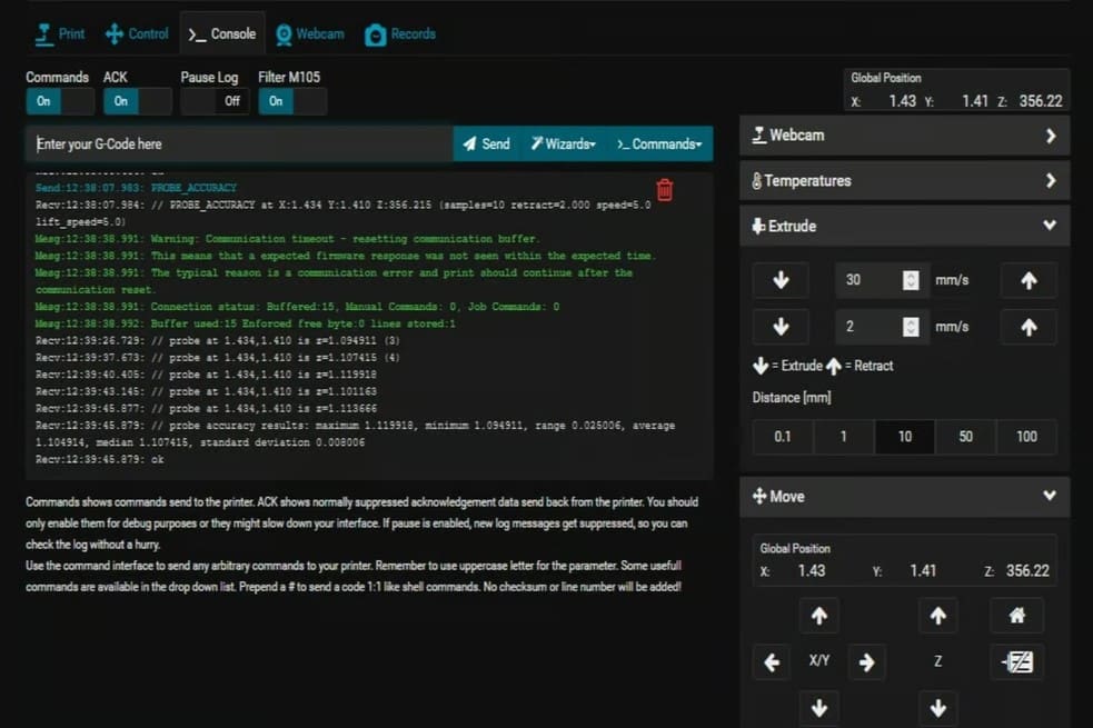
Nozzle Mounted Pressure Sensors
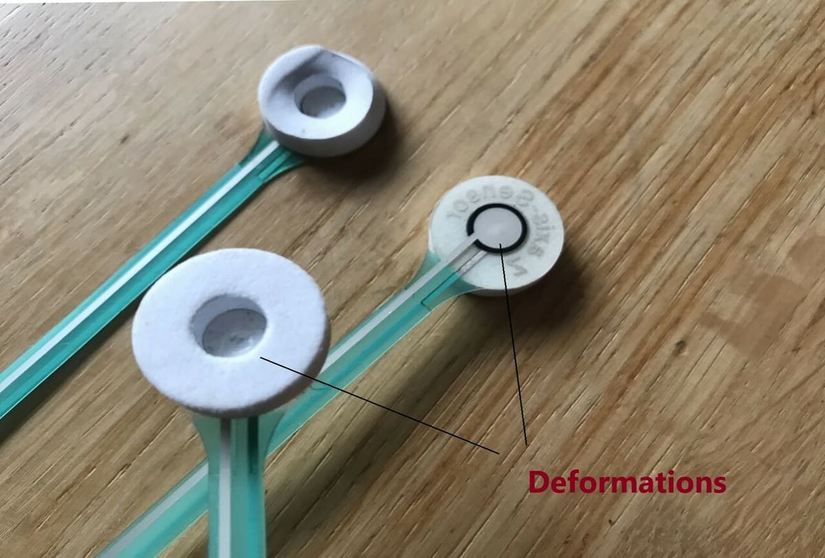
These seemingly simple probes deform over time, thereby changing the trigger point slightly – which again isn’t helpful. The probes can also move very slightly when the foam grabbing the nozzle wears out. Moreover, the nozzle must be clean if we use such a probe because any plastic leftovers on the nozzle will affect the measurement process.
All of that is to say, you may want to consider another probing method if you want to maintain a correct and stable Z offset.
Location Bias
Location bias is another type of bias we can experience, and it can be very hard to rectify. It describes a distortion in probing measurements that are apparent when the probe moves to specific locations on the print bed. Effector tilt in Delta printers is a great example, but location bias can also exist in Cartesian printers.
Klipper recommends dispensing with normal bed leveling procedures if the probing differences at various locations on our print bed exceed 25 microns. The only way to rectify this problem is to address the underlying issues.
How to Do It
The consequences of the problems described in the preceding section are clear. With varying measurements, we obtain a poor representation of our print bed in the form of a mesh. The nozzle is in some areas too close or too far from the print bed on our first layer. Poor adhesion, print bed damage, and skipped steps are all potential results, leading to a failed print.
In order to avoid these problems, we’ll need to ensure the Z offset is correct. In the following section, we’ll explain exactly how to do that.
Preparation
To proceed with calibrating the Z offset, we’ll need the following:
- 3D printer with Klipper firmware installed, working, and accessible via a console (for example, OctoPrint or Repetier, among others)
- An accurate, working probe, tested and installed
- A calibrated printer with a clean level bed and no distorted frame
- A clean nozzle free from plastic residue
- A feeler gauge with a 0.1-mm blade or a piece of paper
Just a brief recap of why these points are important. Console access is needed to type in commands for calibration. It can’t be done solely via the 3D printer’s display. The probe has to be matched to the build plate material. For example, an inductive probe can’t see a plastic print bed. A capacitative sensor will deliver variable readings unless it’s sitting in a temperature-controlled environment.
The 3D printer has to be built straight and accurately; otherwise, the entire undertaking is flawed. Calibration cannot compensate for physical shortcomings. If the nozzle is not clean, it’ll interfere with the correct measurement. Lastly, the feeler gauge or piece of paper will be used during the calibration process.
You’ll also need to complete the X and Y offset calibration before the Z offset calibration. Without the XY calibration, the following Z offset calibration simply won’t work correctly, as the nozzle might not move over to the correct spot where the probe has to touch the build plate.
Calibration

Remember what we want to achieve with this calibration: We want to measure the height difference between the nozzle and the trigger point of the probe at room temperature (no heating up). In principle, the Z offset calibration is a two-step process:
- Probe as normal and move the nozzle above the probing point
- Manually lower the nozzle down to the build plate until we feel some friction with the gauge or the piece of paper
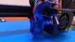
For the first step, open the console, enter PROBE_CALIBRATE, then hit enter. The 3D printer will probe and move the nozzle automatically to the probing point. This is important to avoid any errors introduced by differences in the print bed surface. If it does not do this, check the XY calibration.
For the second step, we use the “paper test” procedure:
- Move the nozzle 2 mm closer to the plate by typing into the console
TESTZ Z=-2 - When already close, use smaller increments until we feel some friction against the feeler gauge or paper. For example, try the command
TESTZ Z=-.1 - If there’s just a little too much or too little friction, move the nozzle half of the previous amount up or down with the commands
TESTZ Z=-orTESTZ Z=+ - Once you’re happy, type in
ACCEPT - Don’t forget to save the new setting. Enter
SAVE_CONFIG
If something goes wrong at any point during the calibration, we can stop at any time by entering the command ABORT.
Troubleshooting
If things don’t work out as expected, stop and think. The “KISS” approach – or “Keep It Simple, Stupid” – usually does the trick.
What has changed since the previous time? Have we changed the nozzle? Have we changed the hot end? Has the printer moved? The idea of this line of questioning is clear: Try to figure out what’s different.
If there has been a physical change related to the hot end, print bed, nozzle, or probe, we simply need to recalibrate, as the Z offset will have changed. Even if we’ve replaced any of the items with identical models, there can be small differences.
If the printer has moved, it’s always wise to check if it’s level and not twisted before calibrating again. If using a capacitive probe, make sure the fan has not been running inadvertently and the ambient temperature has been taken into account.
Most of the issues you’ll see discussed on various chat sites and can be resolved with the line of questioning mentioned above. There are a few actions in Klipper that will invalidate your Z offset calibration, namely running the commands DELTA_CALIBRATE, QUAD_GANTRY_LEVEL, or Z_TILT_ADJUST. The same is true for adjusting the bed level manually.
We’ll end with a note about Z offset and slicer settings. The Z offset is usually a firmware thing, and the slicer has normally nothing to do with it. However, problems can occur if the slicer adjustment for the Z offset is not set to zero. As long as we use an automatic bed leveling probe and everything’s well calibrated, we should not need the slicer’s Z offset adjustment. If your prints fail despite calibration, check the slicer for unwanted Z offset adjustments.
License: The text of "Klipper: Z Offset Calibration – Simply Explained" by All3DP is licensed under a Creative Commons Attribution 4.0 International License.