Klipper: Sensorless Homing – What Is It & How to Set It Up

If you're wondering what Klipper sensorless homing is, look no further! Read how to configure Klipper to home without using endstop switches.
In this article, we’re going to be talking about an interesting topic that relates to how a 3D printer defines its position. However, it makes assumptions about what you, the reader, already know.
Specifically, you should know what Klipper, endstop switches, stepper motors, and stepper drivers are. If you’re unfamiliar with those terms, we recommend you get your bearings first and then come back.
This article is meant as a familiarization guide to help you understand the concepts and to outline the general process of setting up your Klipper-running printer to not use endstops. It’s not meant to be a complete guide to replace the official Klipper documentation on the subject. Rather, the objective is to complement Klipper’s documentation and to explain how and why it works rather than just how to set it up.
After going over a few basic definitions that are worth restating, we’ll get into how sensorless homing works, requirements and limitations of the setup, Klipper configuration, and we’ll wrap things up by going over the pros and cons of sensorless homing.
Let’s get started!
Basic Terms
Before we go deeper, let’s make sure to cover some basic terminology about a few items:
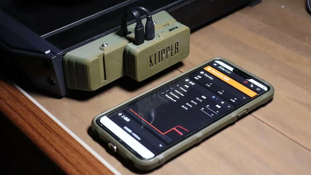
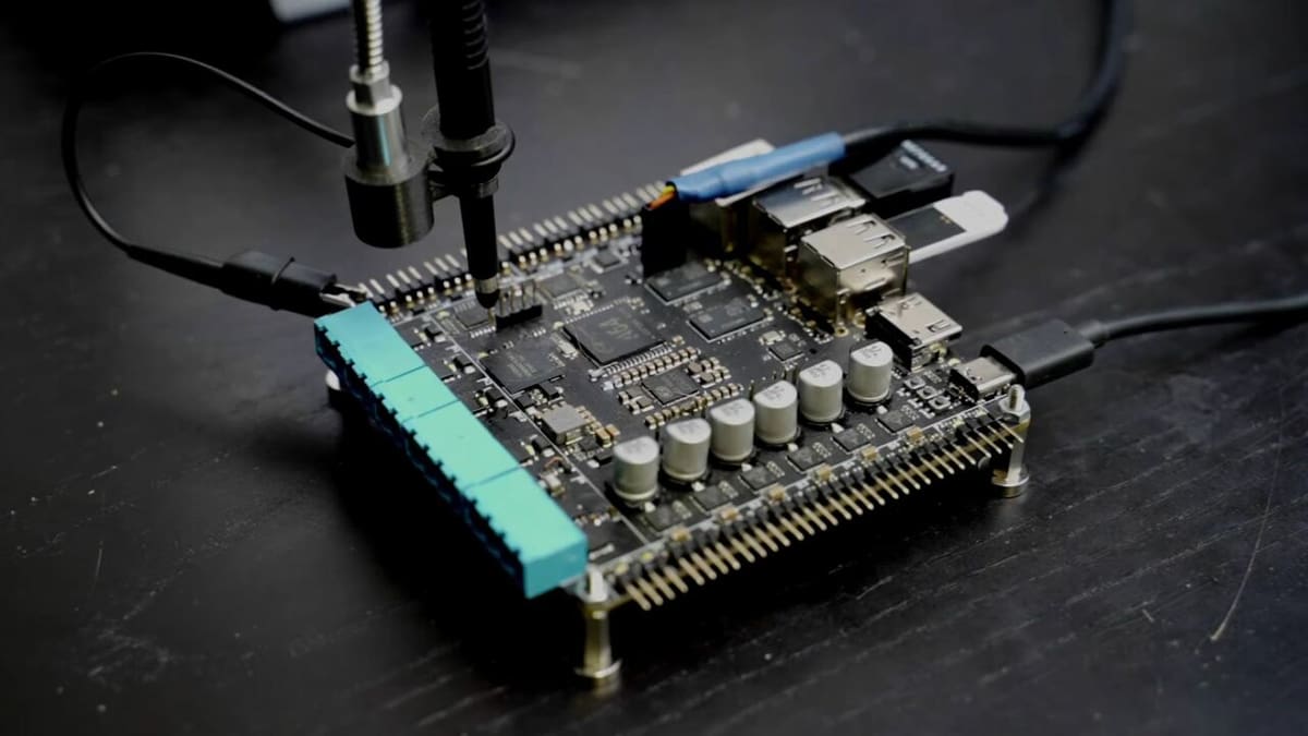
- Klipper: This is an advanced embedded machine control software, a.k.a. firmware. That is, it’s the code that runs many 3D printers, CNC machines, or laser cutters. It evolved primarily for 3D printers, though, and other uses are considered experimental. Klipper is unique in that it needs two different electronic “brains” to run, one is a fast processor that runs a computer (e.g. Raspberry Pi, though you could use any Linux-compatible platform), and the other is an embedded processor (ATMega, STM32, or a similar chip) that need specific programming to run. This allows Klipper to separate the heavier number crunching from the execution of time-sensitive elements.
- Sensorless homing: Most printers use some kind of sensor for the home position detection, the initial movement the printer does to find its reference position. Sensorless homing means finding that home position without any sensor being wired to the printer. While it sounds like magic, it’s really quite precise monitoring of the stepper motor’s efforts.
- Endstop switches: These can be small electrical contact switches (that generally go “click” when pressed); Hall effect sensors, which detect a magnet approaching; or optical sensors, which discern an opaque item blocking a tiny light that the sensor emits. The latter are generally quite wear-resistant and precise but are also more expensive and need more wiring (power pair and signal wires). Contact switches are the cheapest kind and are the easiest to install, and they’re known to have a variable detection threshold of around 0.05 mm. Generally acceptable for hobby machines, they can and do fail over time, either by having an increased variability or simply no longer switching from open to closed or vice-versa.
With the main players described, let’s see how they work together.
How Sensorless Homing Works
As mentioned above, sensorless homing works by precisely measuring variations in the amount of effort a stepper motor is making. How does that work, exactly, and why will this matter? Let’s walk you through it.
Overview of Stepper Function
A stepper motor, unlike a direct motor current you may be familiar with, doesn’t just rotate when you apply power to it. You’ll generally find four wires, and sometimes more going into the body. The reason is that there are generally two separate electromagnet groups in the motor, and they’re wired so that every other magnet is wired together. So, if there are eight coils inside, you’d have a sequence of magnets A-B-A-B-A-B-A-B where A and B are the two phases of the motor.
To turn, a stepper turns on the current one way for magnet A, then B, then A again, which causes the magnet on the rotor to be drawn towards the closest A magnet, then to B, and then next A. By changing the direction of the current going through A or B, the direction changes.
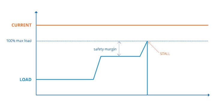
Current Spike When Stepper Stalls
Okay, but why do we need to know this? Well, it turns out that if there’s something preventing the motor from turning (like, say, trying to turn a pulley when the other end is hitting against the edge of the frame), it causes a counter-current in the electromagnets. We won’t go into the depths of electromagnetic theory, so to simplify, think of it as Newton’s law of action and reaction applied to electricity and magnets together. Essentially, it is the voltage and current traveling in the opposite direction.
So, if there’s a certain voltage and current passing through the magnet when the motor is rotating freely, and the rotation gets stopped as the stepper tries to switch magnet coils, you’re going to see the counter-current come into play. This means that the total current and voltage the wires carry will decrease. Now, they’re small percentages of the overall values, but they’re still measurable with embedded sensors.
Detection of Spike by the Driver
More modern stepper drivers (like those of the TMC 2-series) generally include a mechanism to measure these changes and send feedback to the controller board. There are other reasons why the voltage and current measurements may fluctuate during operation, so the control mechanism is configured to send a signal only when a certain threshold is crossed. With 2208 or 2209 steppers from 0 to 255 (TMC2130 or TMC5160 go from -64 to 63) means you go from sending an alert at the slightest deviation (i.e. nearly any stepper movement), to the less sensitive sending a signal at no variation (short of unplugging a stepper, which you should never do while it’s powered).
Requirements
Okay, so we’ve been covering a fair bit of theory and we’ve roughly gone over how the sensorless homing can function. But what are the actual requirements to make it work? Not all printers and not all controller boards can handle it. So let’s look into what you need to set it up.
Up-to-Date Klipper
This one should be obvious, but let’s just state it anyway. You’ll want a reasonably updated version of Klipper, especially given the incredibly fast-changing nature of the controller board availabilities and new releases on the market. The logistics of chip availability have made large, continuous releases of well-tested boards nigh impossible, so the microcontroller unit (MCU) and other components on the boards keep changing. As such, you need to make sure that the Klipper version you’re running will support the MCU you have. If you run an older board, it’s still worth updating as there are continuous improvements happening to the code. The downside is that you may need to update your configuration file as some parameters were completely changed.
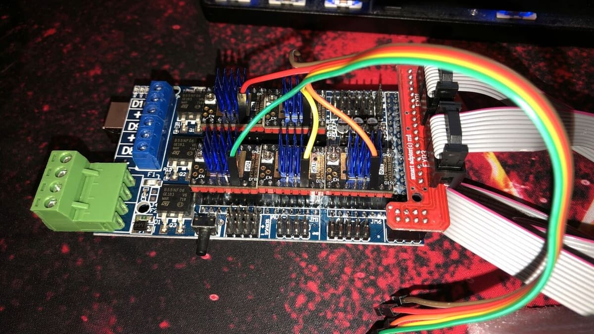
TMC Drivers
At the moment, only Trinamics drivers have the onboard sensors to detect the stepper stalling. The feature is trademarked by TMC as “StallGuard”, “StallDetect”, or “StallGuard 2”, and is generally implemented on all drivers released after the 2130 for the 2-series (2208, 2209, 2660, etc.). Others may include it as well (like the TMC 5160 meant for 48-V applications). The basic information page from Trinamics’ datasheet download will generally include one of the keywords to tell you whether the driver physically supports it and over what protocol. Then you need to read through the step-stick documentation of the ones you bought to see if the stick has enough pins to allow the function to work as well.
UART or SPI Diagnostic Pin Signals Readable by the MCU
First, depending on your setup, your controller board may have SPI or UART bus communication between the MCU and the stepper driver. This matters because while most drivers can communicate on both (one or the other, not both at the same time), some only support one of those communication methods.
Second, you need to have diagnostic signals being sent back to the MCU for the sensorless homing to work. If the MCU just fires instructions at the driver and never reads back the status of the driver, your setup can’t function properly with sensorless homing.
Some older controller boards (like the dated RAMPS) don’t have either option to connect the diagnostic pins to the MCU onboard, so you have to use extra jumper cables to get them connected to free pins. Oftentimes the endstop pin might do the trick. Make sure your controller has the onboard option to do so, if not you’re going to need to get creative in order to connect them in a way that Klipper can use.
Solid Gantry
This last one seems obvious, but don’t overlook it, as the gantry has to be able to hold against the full stepper torque. If you’re running a frame that’s screwed together without threadlock, although it may be suitable for running endstop switches, it probably won’t be steady enough for sensorless homing as it is quite merciless on the hardware. If you don’t calibrate your thresholds quite right, you’ll have heavy impact and strong vibrations being applied to your printer, which will make screws come loose. It’s a matter of when, not if.
Part of the reason why Prusa’s i3 can use sensorless homing well is that the part of the frame that receives the impact is a solid piece of metal with no joints to loosen over time from the strain.
So make sure your frame is sturdy enough to properly stall your stepper, and that repeated impacts and stepper skipping step vibrations won’t eventually shake your frame apart. If screws are holding your machine together, make sure they’re all using thread-locking fluid (the blue is enough).
Limitations
Before we proceed, let’s go over a few of the limitations of sensorless homing, and where you shouldn’t try to use it.
Klipper’s documentation on sensorless homing strongly discourages the use of sensorless homing on delta printers. The reason mentioned is quite clear: sensorless homing doesn’t provide as accurate of a positioning as a sensor. While it’s generally precise enough to make sure you get the nozzle over the bed on a Cartesian or CoreXY machine, you can’t get the same precision that you need for a delta printer.
This is due to the geometry requirements of the delta printer concept as a whole; you won’t really notice or care if you’re 0.1 mm off alignment on your print bed, but you will notice a significant issue on a delta printer’s first layer with the same offset!
The other place to not use sensorless homing is on the Z-axis. The vast majority of printers around use lead or ball screws for the Z gantry, whether it’s the bed moving down or the toolhead moving up. They are precise, reliable mechanisms. But they also transform torque significantly. You’re quite likely to damage components of your hot end if you use it that way.
Pros & Cons
Knowing the limitations, let’s look at the advantages and disadvantages of sensorless homing, because while it sounds great, sometimes there are downsides to it. It’s best if you’ve got a clear picture before you choose whether to move forward with it or not.
Pros
- Less wiring: You can take out all the endstop switches and the wires to the controller. Fewer wires make a machine tidier.
- Usually less likely to fault: If it fails, you probably have an issue with the stepper driver or the motor itself, an issue you could’ve otherwise attributed to a bad switch when that wasn’t the case.
Cons
- Less exact absolute positioning: As discussed above, this makes sensorless homing undesirable for delta printers, or if you have a machine where you need to print really close to the edges of your bed regularly. In those cases, you’ll want to have a much finer position control in play.
- Can be louder: Depending on your printer’s gantry setup and the speeds and thresholds you need, the axis hitting the frame may trigger a loud bang every time. Not exactly ideal for starting prints after the kids have gone to sleep, for example.
- Wear on the frame: If your frame is like those of a Creality Ender 3, with extrusions held together with screws, repeated impact against the frame could partially loosen them. Or if your frame uses plastic parts at the joints, cracking may occur because of an application of stress that is simply beyond what the joints are meant to handle.
Overall, sensorless homing can be a really great solution for some printers when you want reliability – it’s why Prusa i3s have been doing that since the original MK3 came out. But other higher-end printers still use endstops, including those of the Voron community. Ultimately it comes down to price, reliability and how strong the frame is, and how long it takes to fine-tune the sensitivity.
So, if the pros outweigh the cons for you, read on to find out how to change your setup!
Klipper Configuration
Now let’s look at the various elements needed to have Klipper using our stepper drivers as an endstop.
To get it all running, there are two sections in the printer.cfg file we’ll need to take a look at for each stepper where we’re doing sensorless homing:
- The [tmcXXXX stepper_?] section
- The [stepper_?] section
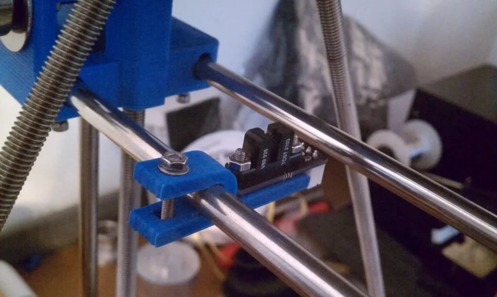
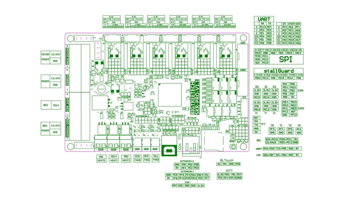
Then to make sure we don’t get things wrong, we need to make sure we know exactly which pin identifier to give Klipper. This will be heavily dependent on your electronics board, so be sure to load up exactly the board you have – not just the model, but the revision too! There are differences between the SKR E3 Mini v2 and v3, so make sure the pinout diagram matches exactly your board’s version!
The picture above shows a BigTreeTech SKR Pro 1.1 pinout where you’ll want to look at the tables on the right. Use the pins in the StallGuard listing to tell Klipper the right diag_pin to use. Different boards have different types of documentation. For example, Intelligent Agent’s Recore wiki page uses a different illustration, as well as a full table below to help guide you through what the Klipper pin configurations should be.
So what do we need to have enabled in the TMC section?
Well, if you had a printer running with endstop sensors before, you already have most of the required configuration sections in place. You’ll only need to add a few lines in the [tmcXXXX stepper_?] section and modify the [stepper_?] section. If you’re setting up a new printer, you’re going to start from a generic config file that includes those lines with the assumption of an endstop definition.
Per the relevant Klipper documentation, here’s what you need to modify (we’re using the TMC2209 here as an example, make sure to match to your hardware as needed!), to have the following lines appear:
[tmc2209 stepper_x]

diag_pin: ^PA1      # Set to MCU pin connected to TMC DIAG pin

driver_SGTHRS: 255  # 255 is most sensitive value, 0 is least sensitive
And then in the next section:
[stepper_x]

endstop_pin: tmc2209_stepper_x:virtual_endstop

homing_retract_dist: 0
Tuning the Parameters
The driver_SGTHRS value in the configuration, as described in the comment on the line, determines how sensitive the threshold detection will be. The higher the value, the more sensitive it will be. But when it’s too sensitive, any friction in the movement will trigger a signal being sent. To home reliably, the configuration needs a value that eliminates all possible false positives but is still low enough that it will immediately detect contact with the hard endpoint of the axis.
There’s a tuning procedure to run where you set the value at runtime and then save the value you settle on in the configuration file. It’s done in three steps.
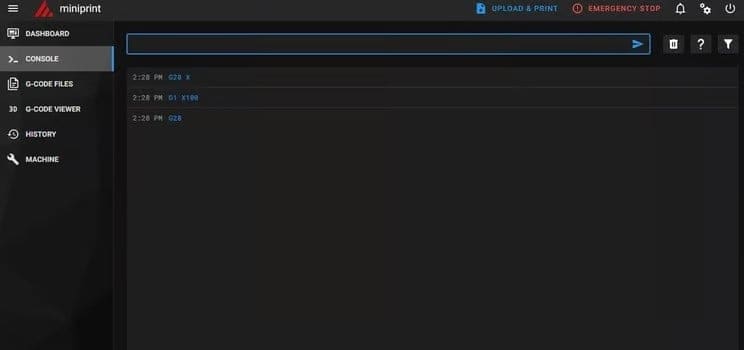
Step 1
Set a new value for the detection threshold. In the console, you’ll issue the following command:
SET_TMC_FIELD STEPPER=stepper_x FIELD=SGTHRS VALUE=255
In the case of TMC2130, TMC5160, and TMC2660, the range of values is different, so be sure to read the Klipper documentation to get it right.
Step 2
Move the relevant axis to the middle of your print volume. For example, if you have a 230 x 230 x 250 mm printer, you’ll want to move ‘X’ to 115 mm by entering G1 X115 F4000 in the console.
If you want to tune the Y-axis, simply change ‘X’ to ‘Y’.
Step 3
Now, you’ll issue a homing command for that axis: G28 X. See if it homes all the way against the frame or if it halts before. If it stops before hitting the frame, the threshold is too sensitive. If it’s grinding while against the frame, it’s not sensitive enough.
Choose a different value for SGTHRS in step 1, then repeat these steps. Usually, a binary search method works fastest: The range is 0 to 255, so pick the value in the middle.
Depending on if it stops too early or too late, you know if you’re going to want to be between 0 and 127 or 128 to 255 respectively. Pick the middle of that range and refine until you get something that works for your machine. You stop when you’ve reached a point where the printer homes several times on the same axis at the frame, without any false positives.
And there you have it! Your Klipper-based printer will be running on sensorless homing.
License: The text of "Klipper: Sensorless Homing – What Is It & How to Set It Up" by All3DP is licensed under a Creative Commons Attribution 4.0 International License.