Klipper & BLTouch: How to Make Them Work Together

With Klipper, BLTouch probes automate the mesh bed levelling process. Read on to learn how to set up and use the BLTouch with Klipper!
For anyone involved with FDM 3D printing, regardless of printer configuration, a level bed is the holy grail for a perfect and reliable first layer. Unfortunately, in the real world, “perfect” rarely exists. Even the flattest of beds can warp, shift slightly, or simply have flaws. The ever-popular removable magnetic print surfaces can potentially introduce surface errors by trapping dust between the build plate and magnetic sheet, thus making the print surface less even.
Modern 3D printer firmware such as Klipper and Marlin allows for a process called auto mesh bed leveling (ABL) by measuring the height of the print surface at different points. The more points we measure, the more accurate the representation of the bed, but it’s simply uneconomical in a computing sense to do so. Therefore, a mesh of the measured points is created, and intermediate points are calculated based on a chosen method. Doing so manually with the paper or feeler gauge method is time-consuming and impractical.
This is where automatic self-deploying sensors come in. They don’t require user interaction and are faster than manual methods. But buyer beware, automatic sensing can be done with different sensors, and it’s important to understand the differences. In the following sections, we’ll explain how to set up ABL in Klipper with the BLTouch.
First, we’ll briefly explore the different types of sensors there are and explain why the BLTouch type sensor is of particular importance here. Then, we’ll introduce ABL in Klipper and the available bed leveling options. The remainder of the article will focus on how to implement the BLTouch in Klipper in easy-to-follow steps. Please note that we’re assuming previous knowledge of bed leveling and a reasonably well-set-up 3D printer. In case you need a refresher, please refer to our articles on bed leveling setup and resolving first-layer problems.

Meet the BLTouch
The BLTouch is a Hall-effect sensor, which determines proximity by detecting the presence of magnetic fields, but there are alternative technologies out there, including induction, capacitive, piezo, and mechanical sensors. The alternatives aren’t perfect, though. Some are dependent on the measured surface being metallic, and others are affected by temperature fluctuations. Accuracy can be an issue, or the sensors are simply not widely available. This is where the BLTouch comes in. It does not suffer from any of those issues.
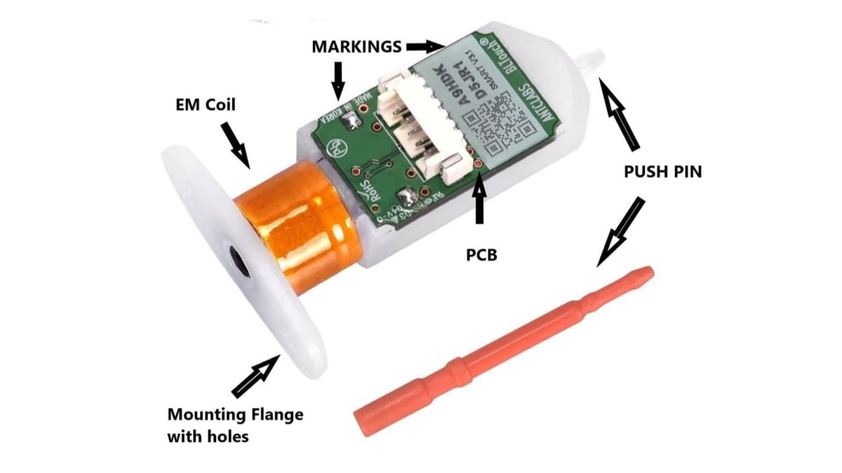
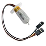
BLTouch original probes are made by Antlabs in Korea, and they have been around since 2015. The probe has undergone further development, and the current version is version 3.1. The sensor features a plastic push pin with a permanent magnet at the upper end, an electromagnetic coil, a plastic body with a mounting flange, and the PCB. As seen in the image, the original BLTouch probes have a QR code on the circuit board as well as the “Made in Korea” print. We mention this because there is a wide range of BLTouch-style fakes out there, some of which work and many that don’t.
All BLTouch probes, as well as their clones, work on the same principle. The coil attracts and releases the touch pin for stowage and deployment. The permanent magnet on the touch pin triggers a signal via the Hall sensor on the PCB, which in turn triggers registration of the nozzle height above the build surface.
The Configurations
Before we get into the nitty-gritty of how to set up BLTouch in Klipper, let’s discuss configuring ABL in Klipper. Their documentation outlines everything you’ll need. In the documentation, Klipper offers up basic settings first, followed by advanced settings.
The idea is that the basic settings will get the user started and set up with basic functionality. The advanced settings add a lot more complexity, but they also allow for fine-tuning, which will be of interest to anybody who wants to improve their print quality.
When setting up a 3D printer, it’s strongly recommended to get the printer working with basic settings first, before adding advanced settings. That way, it’s easier to troubleshoot problems. Also, only change one item at a time for the same reason.
Basic ABL Configuration
As we assume previous knowledge of Klipper and how to access the configuration, we’ll jump straight into ABL and its options. Be aware, ABL is no replacement for poorly built printers and mechanical problems, but it is a replacement for tedious and imprecise manual “paper tests” to establish level beds.
When talking about ABL, we’re talking about the automatic creation of a bed mesh with the intention of automatically compensating for fluctuations in Z height to create the perfect first layer. A bed mesh is a series of Z height measurement points across the build surface. Hence, we start with exploring the configuration settings in Klipper for a bed mesh.
The following is a brief bullet point overview of Klipper’s basic configuration. The settings are slightly different depending on whether your printer has a rectangular or round print bed.
Rectangular
- “speed” is the movement speed of the tool head. The default setting is 50 mm/s.
- “horizontal_move_z” is the movement of the tool head along the Z-axis prior to moving to the next point of measuring.
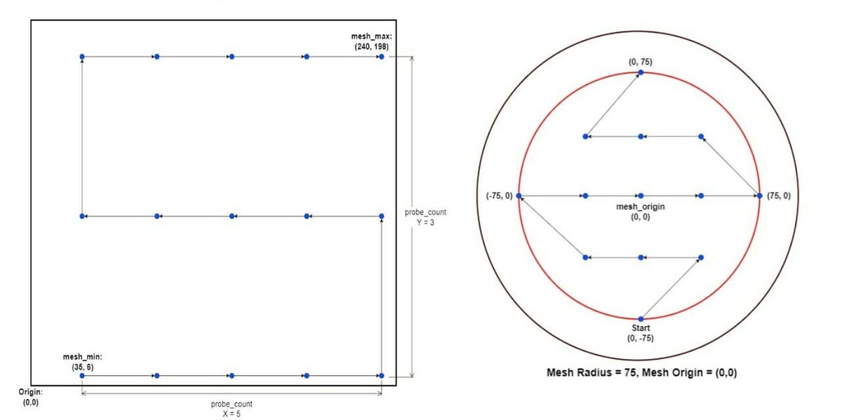
- “mesh_min” represents the coordinates of the first point of measurement relative to the probe location.
- “mesh_max” represents the coordinates of the furthest point of probing relative to the probe location.
- “probe_count” is the number of probing points along the X- and Y-axes respectively. The default setting is 3,3.
Round
- “speed” is the same as above.
- “horizontal_move_z” is also the same as above.
- “mesh_radius” represents the probing radius in relation to the mesh origin.
- “mesh_origin” represents the origin for probing. The default setting is 0,0.
- “round_probe_count” is the maximum number of probing points along the X- and Y-axes respectively. The default setting is 5.
Advanced ABL Configuration
The advanced settings are a little more interesting because they allow for fine-tuning. The functions are divided into five functional groups. As it’s beyond the scope of this article to explain every function in detail, we’ll provide an overview so that you can develop a good understanding of what the functions within the functional groups do.
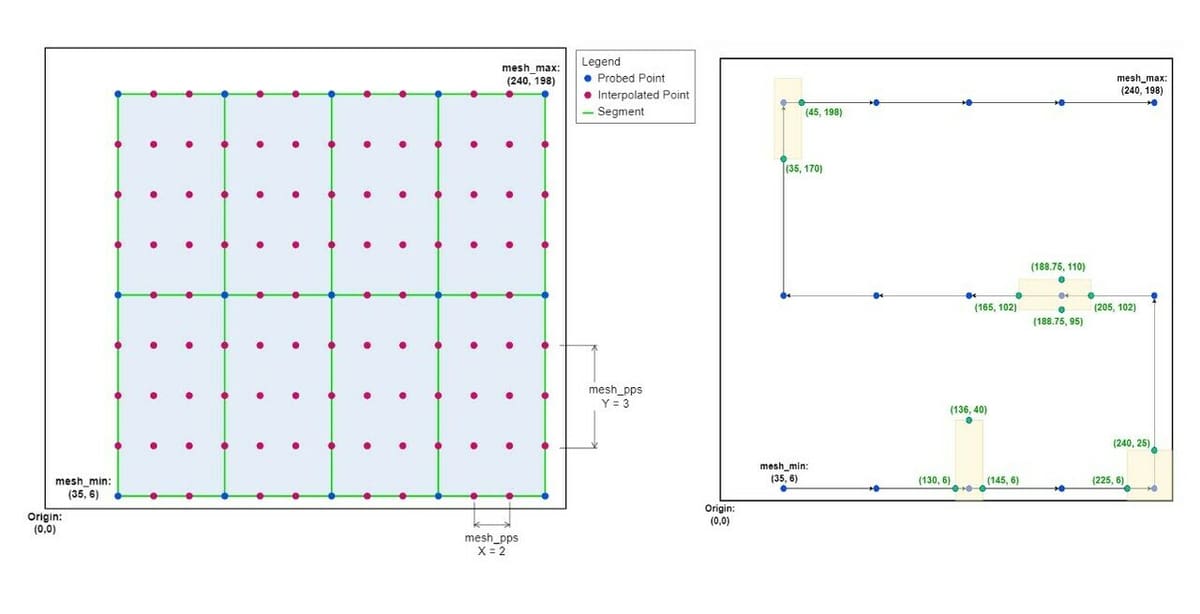
- “Mesh Interpolation” settings provide us with various options to determine how fine a mesh we would like to compute, with additional mathematically derived points between the probing points in our basic configuration. We can determine the number of those additional points along the X- and Y- axes, the mathematical method by which we compute those points (Lagrange and bicubic), as well as a tension factor for the bicubic method that changes the calculated height for the additional mesh points (i.e. it over-exaggerates or under-exaggerates the calculated heights).
- “Move Splitting” allows the user to determine how closely our tool head will follow the calculated mesh by way of setting the distance the nozzle moves before checking against the mesh and correcting the height. We can also set the difference in Z-height, which will trigger a split.
- “Mesh Fade” helps the user to eventually level out the workpiece by reducing the amount of mesh bed correction over a set number of layers.
- “Relative Reference Index” is an interesting setting, as it provides users with probes that tend to drift with a way to automatically adjust the Z-offset based on a reference probing point. This setting is not really needed for the BLTouch, as this probe simply does not suffer from drift or interference.
- “Faulty Regions” allow users to define bed areas where probing results may be faulty, then compensate by probing several times around the edges of such areas.
Setting It Up
Setting up the BLTouch entails a number of distinct sections that we’ll break down into individual steps below. We’ll start with mounting the BLTouch with particular emphasis on mounting height, then will continue to the electrical setup, followed by the software setup.
To complete all of the steps, we’ll need the following:
- A 3D printer with Klipper already installed and functional
- A BLTouch, as well as a mount suitable for the printer
- Cables and possibly extension cables
- The pinout diagram for the controller board showing the pin names
- The dimensions of the print bed
- A marker
- A sheet of paper or a feeler gauge
Mechanical Setup
Mounting the BLTouch is easy. Mounting brackets for most popular 3D printers are available on Thingiverse or can be purchased through online retailers. You could even design your own.
There are a few general things to consider when mounting the BLTouch:
- The BLTouch needs to be mounted perpendicular to the build surface. Otherwise, the probe will not deliver sensible measurements.
- Mount the probe as close as practically possible to the nozzle. It’s always better to keep the offset between the probe and nozzle as small as possible to avoid the introduction of odd artifacts.
- Ensure there’s sufficient space in parking and cleaning positions to avoid damaging the probe.
- Ensure there’s a sensible way to route the cable for connecting the BLTouch to the printer’s controller board.
Mounting Height
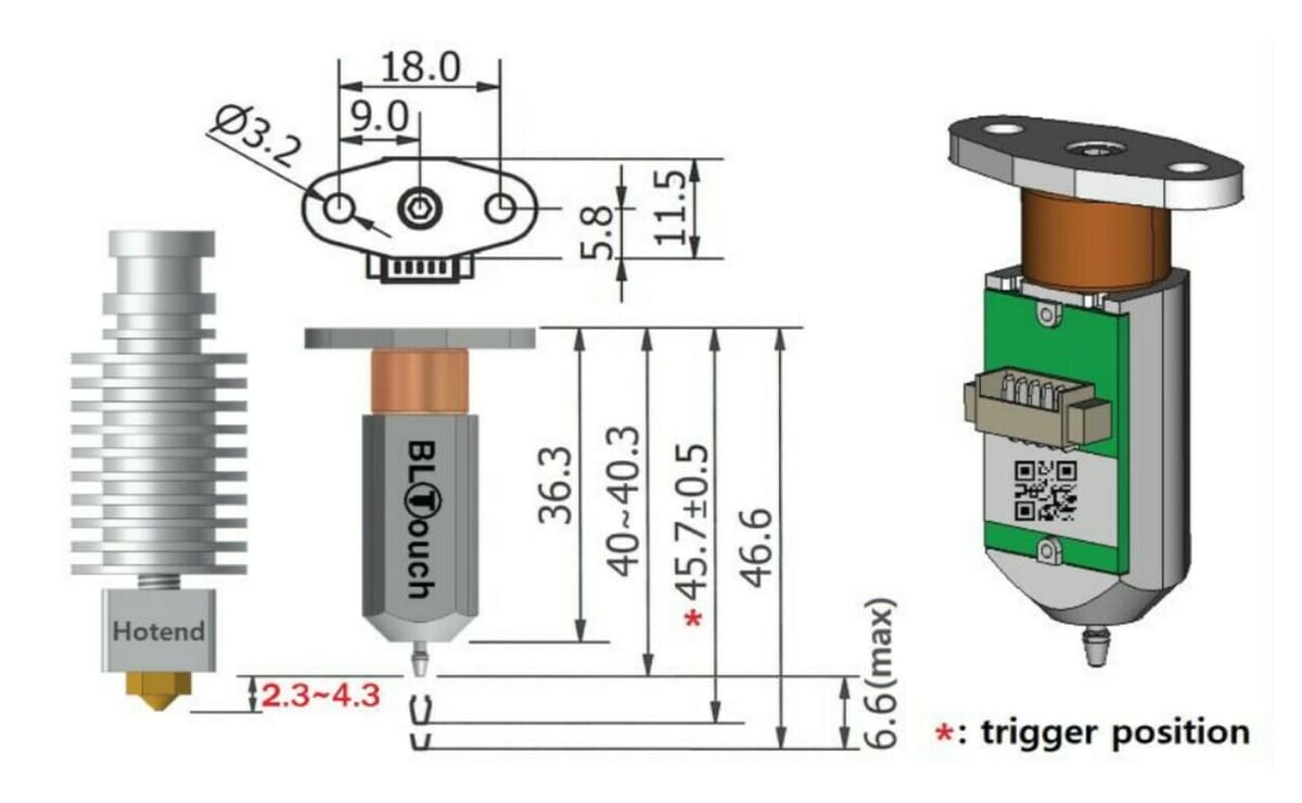
The most important setting for a successful setup of the BLTouch is the mounting height!
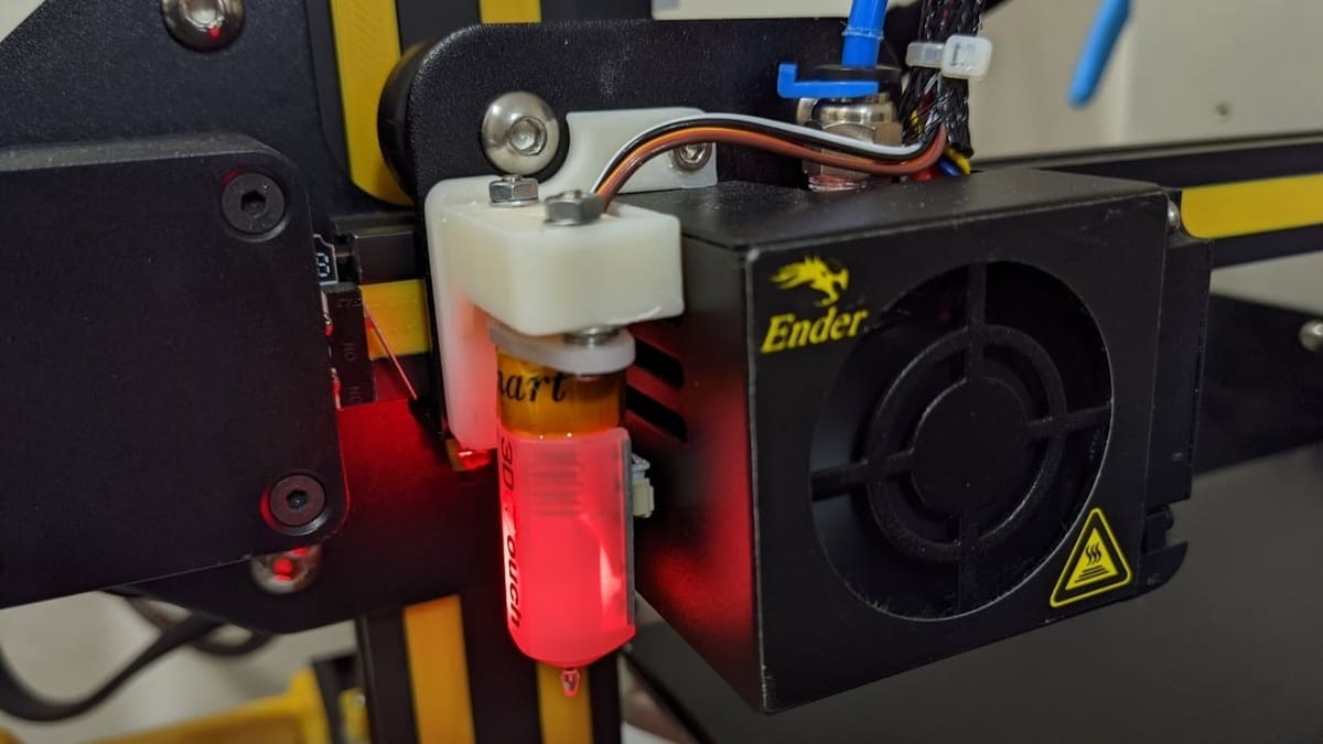
Make sure to mount the sensor at the correct height in accordance with the BLTouch documentation. The image above shows the latest version 3.1, and it’s backward compatible with version 2. The most important dimensions are the push pin drop of 6.6 mm and the height difference between the push pin in the retracted position and the nozzle tip – which should be between 2.3 and 4.3 mm as shown above.
If the BLTouch isn’t configured as recommended, a number of things could go wrong. It’s possible that the sensor will not trigger, allowing the nozzle to hit the build surface (not great). Alternatively, there could be an insufficient clearance in the sensor’s retracted position, which would prevent the nozzle from reaching the build surface at all.
Electrical Setup
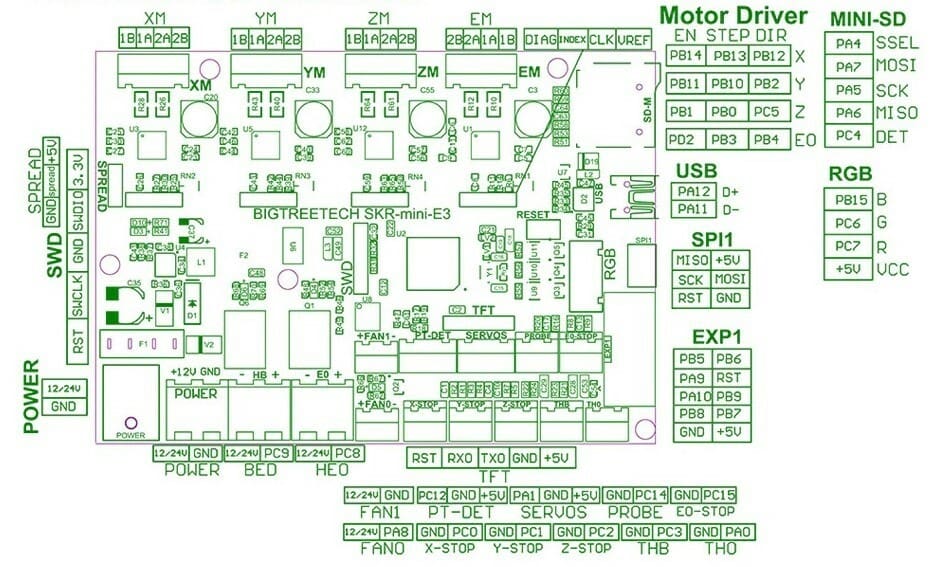
Next, we’ll need to identify the relevant pinouts on our printer’s controller board. Because of the wide range of boards and some users having had problems in identifying the correct pins, Antlabs has kindly provided links with QR codes in the BLTouch manual that lead to sites explaining where to find the correct pins.
The BLTouch probe V3.1 supports 5-V and 3.3-V logic, meaning it supports controller boards that can deal with a 5-V high signal on the input pins (like the Arduino range) as well as those that use 3.3 V (the Esp32 or the Raspberry Pi range of boards, for example). It comes with a white five-pin connector on one end and, at the other end, a two- and a three-pin female plug with the following color-to-pin allocations:
Two-Pin Female Plug
- White: Z-min
- Black: Ground
Three-Pin Female Plug
- Orange: Signal
- Red: +
- Black or blue: Ground
How to Do It
- Ensure that the 3D printer is switched off, and it’s safe to work on.
- Run the connection cable from the BLTouch to the controller board in such a manner that the cable does not interfere with the mechanics and free movement of the printhead.
- Secure the cable with cable ties where needed. If the supplied cable is too short, extensions are available to buy.
- Create the connections according to the pin allocation above.
Tips
On some boards, the order of the connector for the three-pin plug may be different from the cable. In this case, we have to release the wire terminations from the plug and reinsert them in the required order.
In the unlikely event that the controller board is not listed, Google is usually our friend. Use it to search for your controller board’s pinouts. You’ll need the exact label for the servo pin for the BLTouch’s orange signal connection and the Z-min pin for the BLTouch’s white wire. Make sure to note the pin name because you’ll need it later for our software configuration!
Some users reported problems due to electrical interference issues, which can be addressed by using shielded wiring and keeping the connection wires away from other wires. Those reports have to be taken with a grain of salt, though, as a lot of the problems reported are often due to the probe in question being a clone.
As mentioned above, some fake probes work well, while others don’t. As the old saying goes, “You get what you pay for.”
Software Setup
Now that we have mounted the BLTouch probe, it’s ready to be configured. Whatever we use to interact with Klipper – be it Mainsail, Repetier, or others – the configuration process is the same. To complete the configuration, we’ll need the following:
- The board-specific names of the Z-min and servo pins used to connect the BLTouch
- The dimensions and shape of our print bed
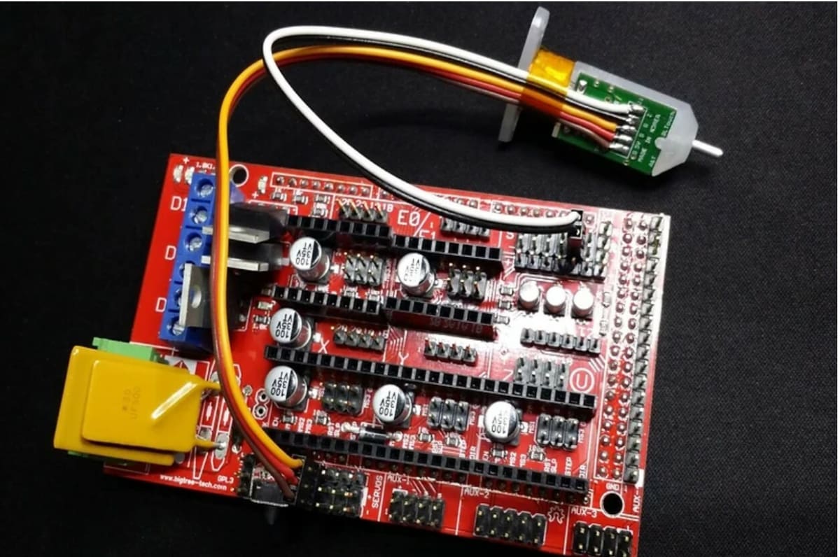
A Ramps 1.6 controller board was used for this example.
How to Do It
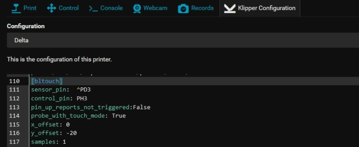
- Open the Klipper configuration, then add (or uncomment if already present) the heading
as shown in the image above. - Under the heading, add the following entries. Remember that the pin name may be different on your board.
sensor_pin: ^PD3control_pin: PH3
- Save your configuration.
- Switch on your printer.
- Restart Klipper.
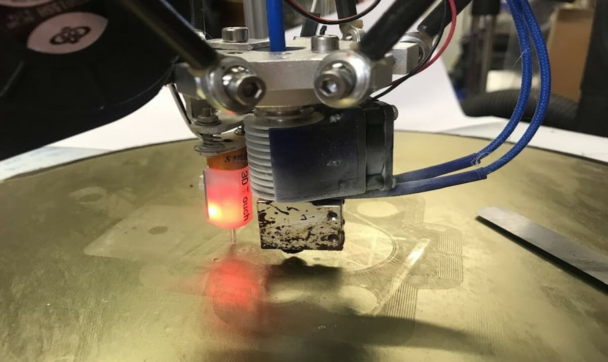
- Observe and check the probe.
During the initial self-test, the probe will retract and drop the pin a few times. It will conclude with the red LED lit and the pin in the up position. Provided the BLTouch passes the initial self-test, all is well.
Regarding the input for the sensor pin, keep in mind that not every BLTouch requires the pull-up resistor to be activated with ‘^‘.
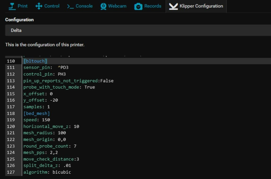
Bed Mesh Setting
Before moving on to testing and calibration, we would recommend to take this opportunity to set up the bed mesh setting as well. While not strictly required to get the BLTouch probe up and running, the entire purpose of this article is to enable our readers to successfully perform ABL, and that requires a mesh.
How to Do It
The following instructions are just to show you how to set up the bed mesh setting. The inputs assume a print bed of 250 x 220 mm with an X offset of 24 mm and a Y offset of 5 mm.
- Open Klipper configuration
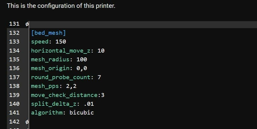
- Add the heading
if not already present - Then, add the following under the heading:
speed: 120horizontal_move_z: 5mesh_min: 35, 6mesh_max: 240, 198probe_count: 5, 3
Again, the entries above are examples to serve as a guide only. The offset you use will need to be determined via the calibration procedure explained in the next section, and your entries must be edited accordingly.
Advanced Configuration
Ignore the advanced settings for now and keep things simple to start with. Once all is well and working as it should, then feel free to experiment with the advanced settings and fine-tune your printer. When you’re ready to do so, we strongly recommend changing one setting at a time to see the effect.
Testing & Calibration
We have now installed the BLTouch on our printer, but we still need to test, calibrate, and eventually troubleshoot our new probe. In the next few sections, we’ll explain step by step the test procedure as well as the calibration process. At the end, we’ll offer some tips on troubleshooting.
Testing

We need to test the probe function without risk of damage to the printer. To do so, we’ll send a number of commands, one after the other in the order below via our command terminal to the printer.
Test 1
Let’s start by sending several commands.
- Send
BLTOUCH_DEBUG COMMAND=pin_down. The pin should move down, and the red LED should be off. - Send
BLTOUCH_DEBUG COMMAND=pin_up. The pin should move up, and the red LED should be on. - Then, send the following:
BLTOUCH_DEBUG COMMAND=pin_downBLTOUCH_DEBUG COMMAND=touch_modeQUERY_PROBE
- After sending the last command, verify that it reports
probe: open
Test 2
Next, gently push the pin up by a few millimeters. Then, send the command QUERY_PROBE and verify it reports probe: triggered.
After that, send the command BLTOUCH_DEBUG COMMAND=pin_up. The pin should move up.
Test 3
For the last test, please be ready to switch off the printer in case of malfunction. Send the command PROBE.
Let the push pin touch something at a safe distance from the print bed. Depending on setup, it might probe twice or more times. The printer should stop as intended.
If all works as intended, we’re done with the basic setup for the BLTouch. If the LED flashes or the pin is down at the end of the test, check out the troubleshooting notes below for guidance.
Tips
Under normal circumstances, the probe should be working now as intended. If the probe doesn’t behave as it should check over the setup again step by step. This includes ensuring all relevant cables and connectors are connected as they should be.
For users with less common controller boards, check the many forums out there for possible solutions. Lastly, if the probe is not an original BLTouch, there’s the possibility that the probe simply doesn’t work. In such cases, we recommend that you get the original.
Calibration
Now that we’re certain that the probe works as intended, we need to calibrate the X, Y, and Z offsets. Probe calibration is well documented by Klipper, but we provide a brief run-through.
Step 1
Via the terminal, issue the command PROBE, then physically mark the position where the probe touches the bed with a marker.
Next, send the command GET_POSITION. You’ll receive something back like the following:
Recv: // : X:46.500000 Y:27.000000 Z:15.000000 E:0.000000
Note down the X and Y positions as “probe x” and “probe y”. Using the example above, the notes should look similar to the following:
- probe x= 46.5
- probe y= 27
Step 2
For the next step, we need to move the nozzle to the marker by using G1 commands. Several commands may be needed before being perfectly centered on the marker. The X and Y will be different for everyone, but to illustrate the command format, it would look something like the following: G1 F300 X30 Y30 Z10
When the nozzle tip aligns perfectly with the position of the mark we made previously, send the command GET_POSITION. This time, note down the X and Y positions as “nozzle x” and “nozzle y”.
For example, if you received Recv: // : X:60.500000 Y:60.000000 Z:15.000000 E:0.000000, you’ll note down nozzle x= 60.5 and nozzle y= 60.
Now, you can calculate the X and Y offsets. The formula is simply nozzle x – probe x and nozzle y – probe y. In our example, the offset is x=14 and y = 33.
Lastly, in the configuration file under the heading, add offsets as follows:
x_offset: 14y_offset: 33
Step 3
Almost there! The last calibration step is finding the Z offset. Klipper offers a command to do that easily. First, we home our printer, then run PROBE_CALIBRATE. It’ll do one automatic probe, then move the nozzle over the probe point before going into the manual probe tool.
Most Klipper users will be familiar with paper test:
- Put a sheet of paper or the 0.1-mm blade of a feeler gauge between nozzle and bed.
- Adjust the Z height up or down with the TESTZ command until there’s a little friction felt when moving the paper or feeler gauge. For example, to move the nozzle up or down by .1 mm, you would enter the following:
TESTZ Z=+.1TESTZ Z=-.1
- When you’re satisfied with the results, type
ACCEPTin the terminal. - Finish with
SAVE_CONFIG, then restart the printer.
Step 4
We’re finally ready for our first mesh. Type BED_MESH_CALIBRATE into the terminal and enjoy!
Once the automatic bed mesh probing has been created, we’re prompted to SAVE_CONFIG. This will save the mesh in our configuration for future use.
Don’t forget to set up the relevant mesh command in your slicer. Otherwise, it won’t be included in the G-code we generate.
Troubleshooting
We can run into a number of problems with the BLTouch, and there are further tuning steps that may be of interest to the discerning user. Below, we’ll recommend solutions to the most common problems. Remember also to check out Klipper’s documentation for the finer points of ABL that are beyond the scope of this article.
Problems During Testing
The most obvious issues are indicated by the BLTouch’s red LED flashing fast or the pin being down at the start of the printer. If we find the above, it’s most likely a wiring issue. Check all connections, then try again. Note that, there have been instances when a BLT is wired backward.
If the red LED flashes or the pin is down when it shouldn’t be during the initial testing, please check the wiring as well as the configuration again. Are the pin names correct? Has a pull-up resistor been specified?
Error State
Occasionally, the BLTouch can go bad for no obvious reason and enter an error state, indicated by a flashing red LED. To exit the error state, type BLTOUCH_DEBUG COMMAND=reset into the terminal to reset the probe.
The exact same error can happen when the push pin fails to deploy because it doesn’t detach from the metal insert at the top of the probe. Fortunately, the push pin can be pulled out, and the metal insert can be adjusted with a little hexagonal key. Just open the screw a little and reinsert the pin gently. Then, try again with the following commands until it works:
BLTOUCH_DEBUG COMMAND=resetBLTOUCH_DEBUG COMMAND=pin_downBLTOUCH_DEBUG COMMAND=pin_up
Clones
If we’re dealing with a clone or a fake, there are numerous other issues that can arise. Klipper offers a range of solutions in their BLTouch documentation under the “BL-Touch ‘clones'” heading.
License: The text of "Klipper & BLTouch: How to Make Them Work Together" by All3DP is licensed under a Creative Commons Attribution 4.0 International License.
CERTAIN CONTENT THAT APPEARS ON THIS SITE COMES FROM AMAZON. THIS CONTENT IS PROVIDED ‘AS IS’ AND IS SUBJECT TO CHANGE OR REMOVAL AT ANY TIME.