G-code Tutorial for CNC Programming: 6 Simple Steps

G-code is everywhere, from 3D printing to CNC. Easily learn the basics of CNC programming with this G-code tutorial in six simple steps.
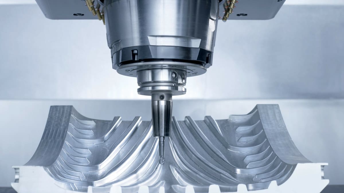
CNC stands for computer numerical control. It’s a process used to automate control of certain machinery, such as CNC mills and lathes as well as additive manufacturing machines such as 3D printers. G-code stands for “geometric code” and this is the language most CNC machinery uses.
Programming G-code might sound intimidating at first, but we’re here to help with the basics. Programming is a fundamental skill for all types of CNC machinery, not just CNC mills. While programs used to design parts for CNC milling, such as Autodesk Fusion 360 and SolidWorks CAM, can create G-code without you ever touching the keyboard, understanding how to use G-code will not only let you write your own custom programs but also troubleshoot when a machine fails.
Every machine uses a slightly different type of G-code, so a Fanuc G-code won’t work on a Haas controller; however, the basics are the same. So let’s dive into the details of programming CNC milling G-code!

Coordinate Systems
Additive machines, such as 3D printers, build parts from the ground up, so they always start from the build plate no matter the part geometry. CNC mills, on the other hand, can start basically anywhere in the machine build space, so letting your machine know the location of the stock material is crucial, otherwise, your machine will just be lost.
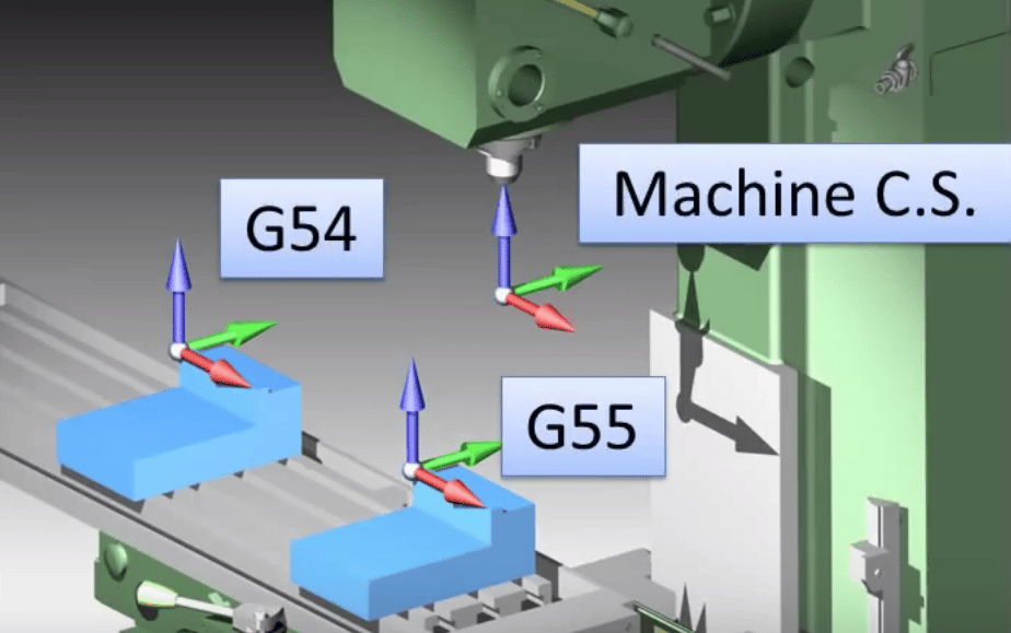
CNC machines each have their own coordinate system with a fixed origin. “Homing” your CNC mill will hit the limit switches on the X-, Y-, and Z-axes, but this point is usually tedious to work with.
In contrast, the work coordinate system (WCS) defines an origin point anywhere the programmer wants. This is usually set by the G54 command, which offsets the machine coordinate system.
Plane Designations
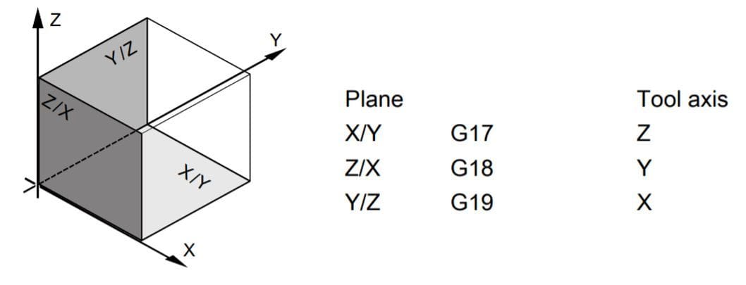
In CNC milling machines, you have three planes defined by the main three axes of the machine: X/Y, X/Z, and Y/Z. Yet, as the number of axes on a milling machine increases, things start to get more complex –for example, the additional rotation movements as seen on something like a 6-axis CNC machine. Defining the plane in which the machine will be working is crucial for it to know where to mill and how to calculate offsets correctly.
Once the machine knows in which plane to work and the operator has dialed in the new WCS (via probing, an edge finder, or using dial indicators), the machining process can start. The action of dialing the WCS into the machine is commonly known as “zeroing” the machine.
Command Structure
G-code is a variation of an alphanumeric pattern. A standard G-code command conforms to the following logic:
N## G## X## Y## Z## F## S## T## M##
Nis the line number the program is in and it ensures that the program follows a logical order.Gindicates a motion using the Cartesian coordinates that follow. There are many G commands (hence the name G-code) and they vary from machine to machine, so make sure to check your controller manual. Nevertheless, there are three basic types of G-codes:G00is used for rapid, non-cutting movements.G01is used for linear movements at a programmed feed speed, usually used to cut material.G02is used for circular movements at a feed speed.
X Y Zcommands are used to define X, Y, and Z coordinates. The Z-axis is the “scariest” to program and the one we recommend being extra careful with, as crashing a machine spindle is always an expensive fix. This is where simulating comes in handy. (More on that later.)Fstands for feed rate, which is basically how fast the machine should move from point to point. It’s usually expressed in inches/minute or mm/minute.Sis spindle speed, which determines how fast the spindle should rotate in rotations per minute (rpm).Tis used for tool selection; most CNC mills now have 10 or more tools ready to use on the machine.Mare miscellaneous functions to turn things on and off, flood coolant, air blast, close machine doors, and more. Every machine has different M commands, so make sure to read your machine’s manual carefully.IandJare used for arcs. The X and Y coordinates of where the arc ends are needed as well as the X and Y distances from the arc start point to the arc center point.
Take a look at the following G-code example:
N2 G01 X10 Y20 Z5 F300 S3000 T1
Breaking it down, we can determine that
- the program is in line 2;
- the spindle is going to perform a feed move (G01) from (X0, Y0, Z0), the starting position, to (X10, Y20, Z5);
- the selected tool is tool 1 (T1);
- the feed speed is 300 mm/min (F300); and the spindle rpm is 3000 (S3000).
Easy, right? A great G-code guide can go a long way when you get lost in what each G-code segment means.
Something you may be wondering at this point is whether CNC milling G-code uses absolute or relative positioning. In fact, you can use either, and this is something we’ll have to tell the machine, but for now, let’s assume absolute positioning. This will be expanded on in the following section.
Absolute vs. Relative
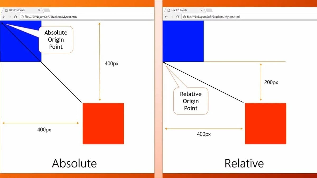
Let’s assume all coordinates are given in millimeters. When giving coordinates, for example “X10”, there are two ways the machine could interpret this instruction. The machine could move to coordinate 10 mm in the X-axis from the origin, or it could move 10 mm in the X-axis from its current position. The first option is called “absolute positioning”, meaning that all coordinates are fixed according to an origin point. The second option is “relative positioning”, meaning the coordinates are parting from the current position.
To explain this further, absolute positioning indicates a position to move to, and relative indicates a distance. For example, if we’re at X2 and we indicate “X4” in absolute positioning, the final coordinate will be X4. If we’re at X2 and we indicate “X4” in relative positioning, the final coordinate will be X6 – you’ll have moved 4 mm from the previous position.
You can change between absolute and relative positioning using G-code. G90 sets it to absolute and G91 to relative. This is especially important when zeroing, meaning finding the zero point or home of your machine, as you don’t know the origin point at that stage, therefore you move in increments.
Program Logic & Cycles
To understand G-code, you need to know how a program is formatted. G-code programs keep to the following structure:
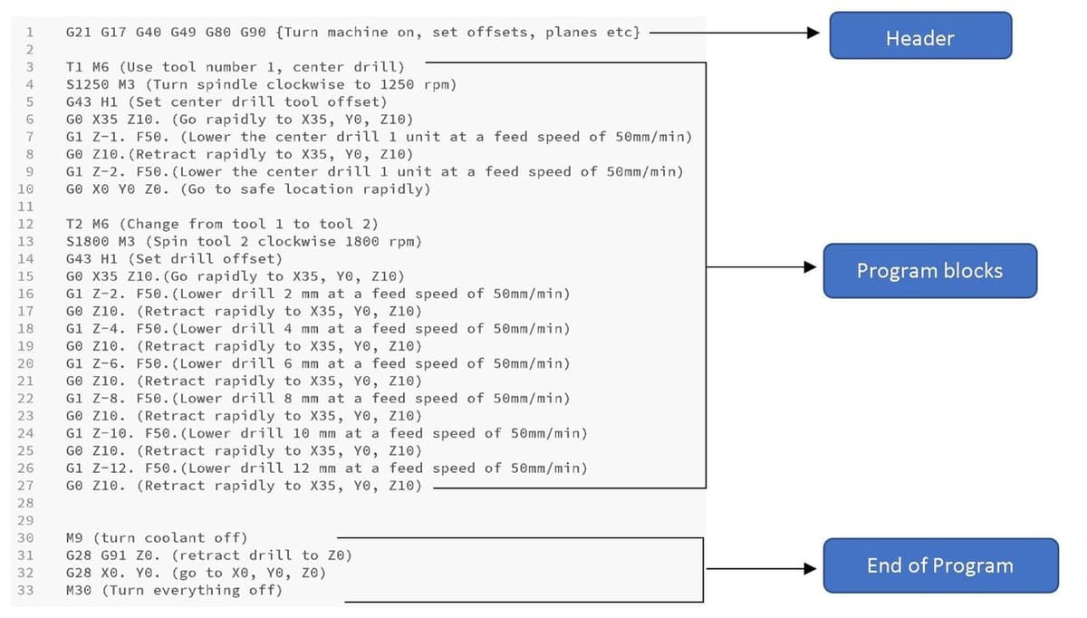
- Program header: This starting G-code basically tells the machine how to prepare itself for the upcoming job. Common aspects include stock dimensions, offsets, and planes.
- Program blocks: Also called the body of the program, this is where the main part of the job is described, including axis moves, speeds, feeds, and tool changes. Codes following the logic described in the previous section go here. (Most errors also appear here.)
- End of program: This part tells the machine that the work has ended so it can retract to a safe position and turn everything off.
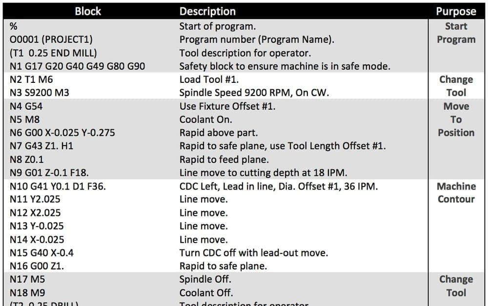
The above image presents an example of these program sections, but it also shows something else. As you can see, the lines have very little variation, only the Z coordinates are changing, while everything else remains the same. This is called a cycle.
Basically, a cycle is a group of simple operations that together form complex movements, like 3D contours, drilling, ramping, and slotting. In this particular example, the code incorporates a center drilling cycle followed by a peck drilling cycle.
Your First CNC Mill G-code
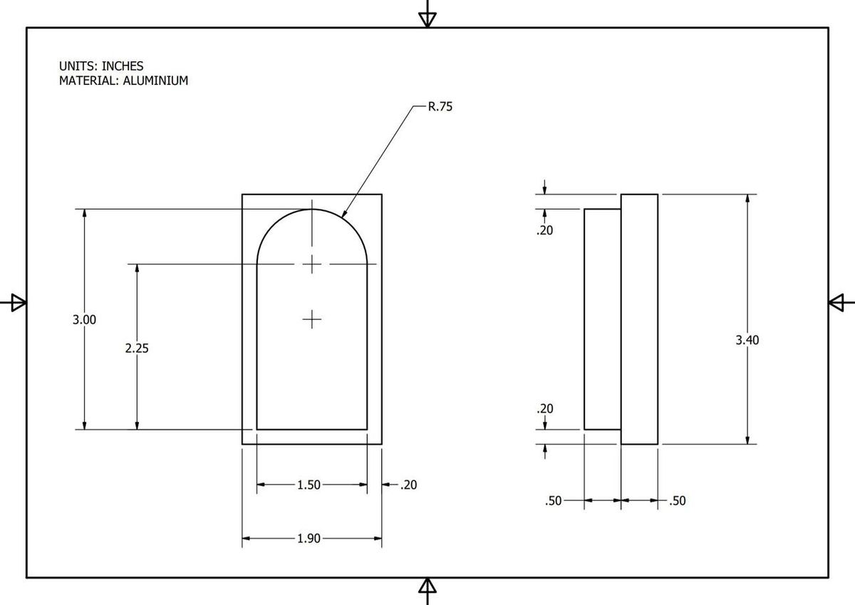
Now that you’ve got the basics, writing a simple program should be easy. Let’s say we want to contour mill the part in the above drawing with a ½-inch mill. All measurements are expressed in inches (no conversion needed), so let’s get to it!
Setting the Work Coordinate System

This first step consists of defining where we want the “Zero” or “Origin” point of the process to be. If you’re doing it in CAM software, how you do so varies depending on the program. However, we’re doing this example manually to explain how G-code works. This step isn’t actually written anywhere on the G-code, but it’s something you need to decide about your design given that all coordinates part from here.
When deciding where to locate the Work Coordinate System (WCS), take into account that this point will also have to be located on the physical stock of material to be machined. It can be wherever you want it, but generally you should think of a place that’s easy to locate physically and that will simplify your G-code, such as a corner or the center of a drawing or circumference.
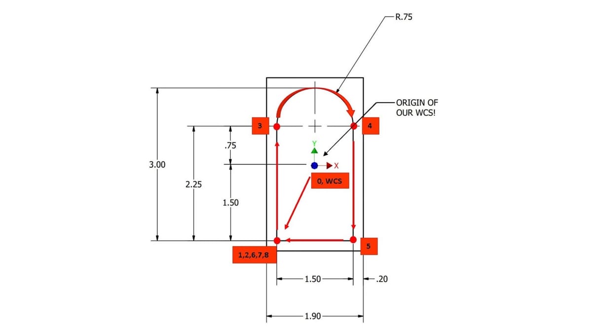
For the example we’re solving, the WCS will be at the exact center of the part.
Ordering Your Path
As with any other programming language, solving a problem with CNC mill G-code can be done in many different ways. That said, optimal machining paths, which make a program as efficient as possible, should always be the programmer’s goal. Generally speaking, efficiency equates to the fewest possible lines of code.
The way you order your path will directly affect what the program will look like. Using the drawing as a guide, we’ll program for the following path, where each line is an instruction that we’ll later translate to G-code. Remember we’re using absolute positioning and starting from the center of the figure, so anything below the center and to the left of the center will be in absolute coordinates. This is also why you need to indicate both coordinates, X and Y, even if your translation will only be in one direction.
- This is where the program will start. As the position (X0, Y0, Z0) is implied, no G-code will be necessary.
- Move rapidly and diagonally to the starting point, located at (X-0.75, Y-1.5).
- Plunge rapidly to Z-0.5, the desired depth of the contour.
- Move linearly up at feed speed to (X-0.75, Y0.75).
- Move at an arc to (X0.75, Y0.75). For this edge, we also need the X and Y distances from the beginning of the arc to the center of the arc. For X, this is 0.75 (
I0.75), and for Y, this is 0 (J0). - Move linearly down at feed speed to (X0.75, Y-1.5).
- Move linearly left at feed speed to the starting point (X-0.75, Y-1.5).
- Retract rapidly to a safe point Z0.
- Move rapidly to (X0, Y0).
Translating to G-code
Essentially, the body of the program should have a total of eight lines for the desired contour. Once our path has been chosen, translation from instructions to G-code language will look as follows:
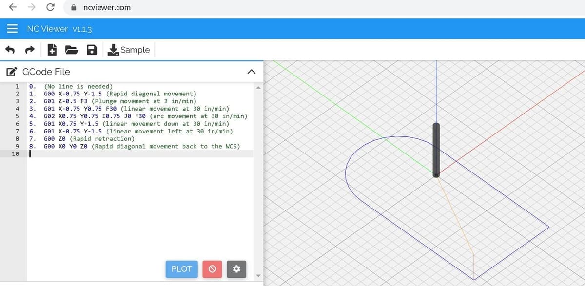
G00 X-0.75 Y-1.5This line moves the spindle rapidly (G00) from (X0, Y0) to (X-0.75, Y-1.5).G01 Z-0.5 F3This line plunges the spindle (G01) from Z0 to Z-0.5 at a feed speed of 3 in/min (F3).G01 X-0.75 Y0.75 F30This line moves the spindle (G01) from (X-0.75, Y-1.5) to (X-0.75, Y0.75) at a feed speed of 30 in/min (F30).G02 X0.75 Y0.75 I0.75 J0 F30This line moves the spindle in an arc movement (G02) from (X-0.75, Y0.75) to (X0.75, Y0.75) with a radius of 0.75 inches (I0.75) at a feed speed of 30 in/min (F30).G01 X0.75 Y-1.5 F30This line moves the spindle (G01) from (X0.75, Y0.75) to (X0.75, Y-1.5) at a feed speed of 30 in/min.G01 X-0.75 Y-1.5 F30This line moves the spindle (G01) from (X0.75, Y-1.5) to (X-0.75, Y-1.5) at a feed speed of 30 in/min (F30).G00 Z0This line moves the spindle rapidly (G00) from Z-0.5 to Z0.G00 X0 Y0This line moves the spindle rapidly from (X-0.75, Y-1.5) to (X0, Y0).
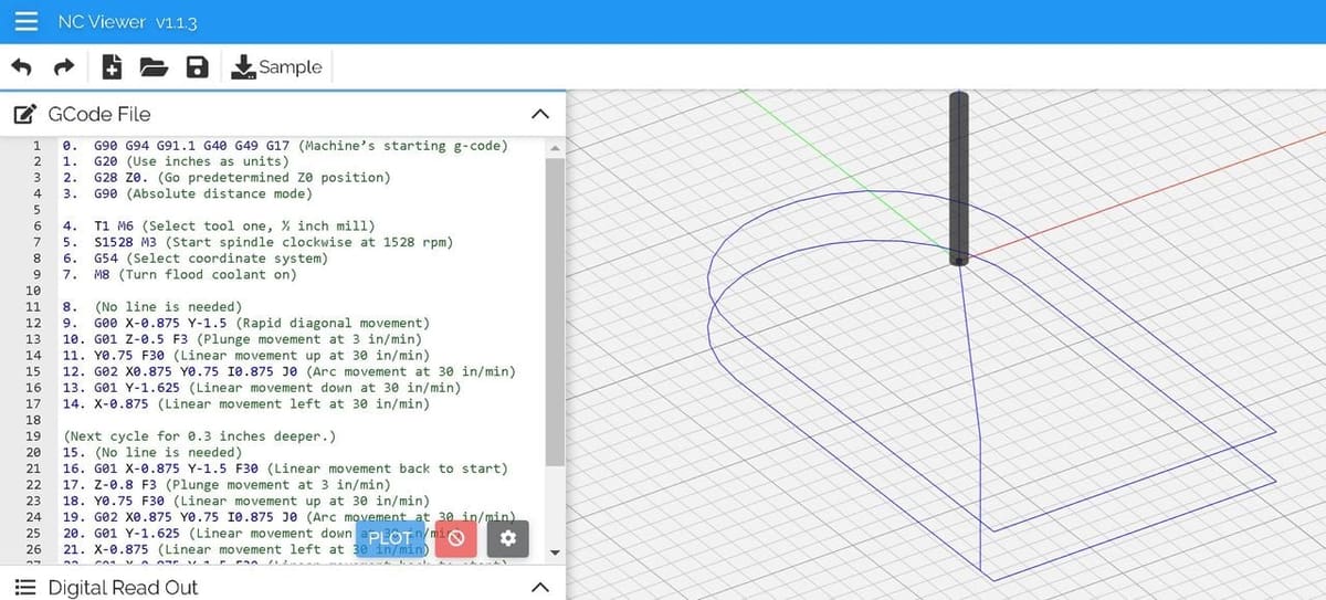
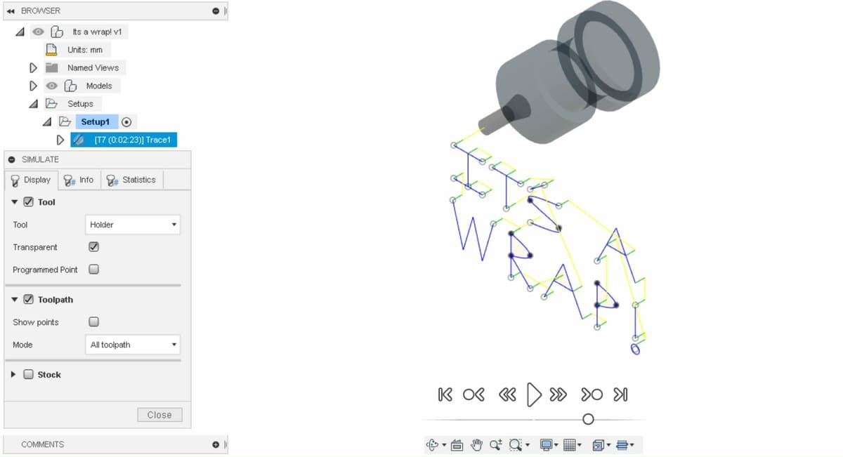
Now it’s time to simulate! Numerical control (NC) simulation is super important, as you need to test what you’ve done in order to know that the movements are correct (and that you won’t run into dangerous or expensive problems). If you’re not familiar with NC simulators, we recommend you take a look at NC Viewer, which is a great free online NC simulator.
Setting the Tool Offset
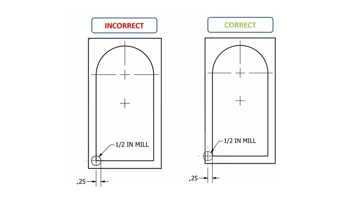
In the image above, notice that the mill passes the contour right on the center, meaning that the final measurements won’t be the actual desired measurements, but smaller. To solve this we must apply an offset.
In the example, the mill used has a diameter of 1/2 in. We should apply an offset to take out the half of the tool that’s working inside the contour. To fix this, an offset of 0.25 inches (half the tool diameter) to the corresponding sides of all coordinates is necessary. Contours on the left need to be offset 0.25 inches to the left, contours on the right need to be offset 0.25 inches to the right, and contours up and down need to be offset 0.25 inches up and down, respectively. Applying this, the resulting program should look as follows:
G00 X-1 Y-1.5(Rapid diagonal movement)G01 Z-0.5 F3(Plunge movement at 3 in/min)G01 X-1 Y1 F30(Linear movement up at 30 in/min)G02 X1 Y0.75 I1 J0 F30(Arc movement at 30 in/min)G01 X1 Y-1.75(Linear movement down at 30 in/min)G01 X-1 Y-1.75(Linear movement left at 30 in/min)G00 Z0(Rapid retraction)G00 X0 Y0(Rapid diagonal movement back to the WCS)
Writing Cycles
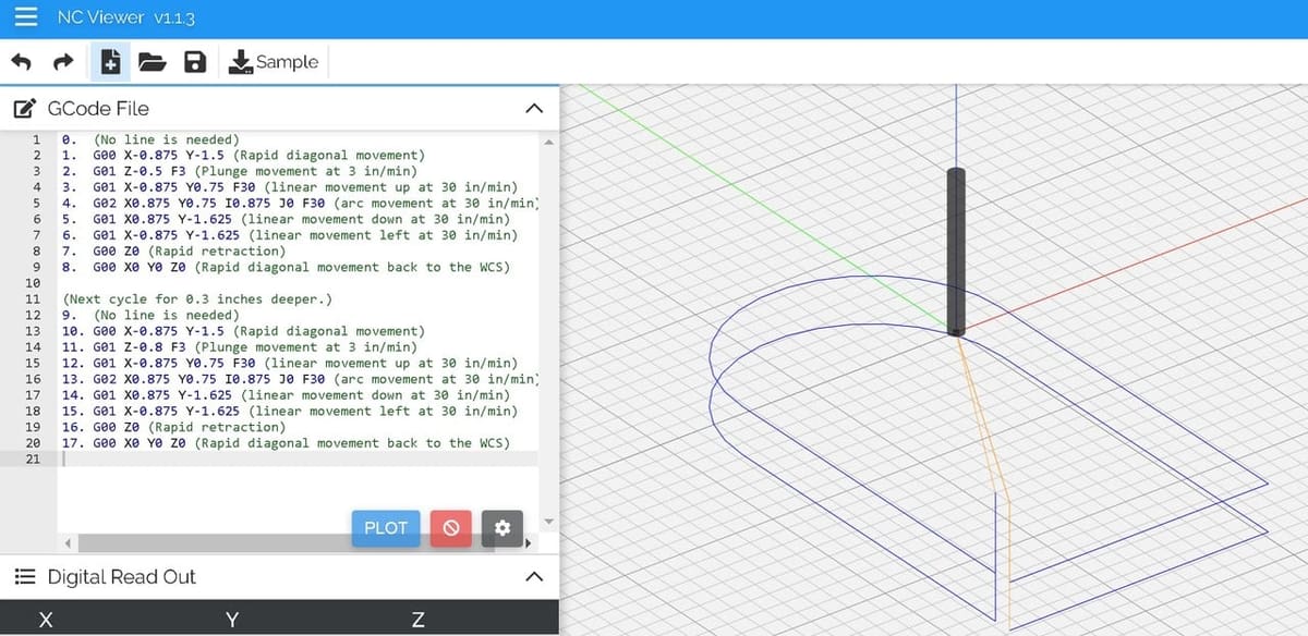
Let’s say that, instead of a contour depth of 0.5 inches, a 0.7-inch contour is desired, 0.3 inches deeper than the original program. All that’s needed is to repeat the program and add “-0.3” to the Z coordinate in line 2, resulting in G01 Z-0.8 F3. Everything else remains the same!
Why not just do this from the start? Because milling at high depths at once will cause extreme forces that may very likely break your tool. The best practice is instead, when you need great depths, to go little by little, adding passes of increased height.
G00 X-0.1 Y-1.5(Rapid diagonal movement)G01 Z-0.5 F3(Plunge movement at 3 in/min)G01 X-1 Y0.75 F30(Linear movement up at 30 in/min)G02 X1 Y0.75 I1 J0 F30(Arc movement at 30 in/min)G01 X1 Y-1.75(Linear movement down at 30 in/min)G01 X-1 Y-1.75(Linear movement left at 30 in/min)G00 Z0(Rapid retraction)G00 X0 Y0(Rapid diagonal movement back to the WCS)- (Next cycle, 0.3 inches deeper)
G00 X-1 Y-1.5(Rapid diagonal movement)G01 Z-0.8 F3(Plunge movement at 3 in/min)G01 X-1 Y0.75 F30(Linear movement up at 30 in/min)G02 X1 Y0.75 I1 J0 F30(Arc movement at 30 in/min)G01 X1 Y-1.75(Linear movement down at 30 in/min)G01 X-1 Y-1.75(Linear movement left at 30 in/min)G00 Z0(Rapid retraction)G00 X0 Y0(Rapid diagonal movement back to the WCS)
Adding the Final Touches
Now that the body of the G-code is done, the header and end of program G-code can be added. Some trimming also doesn’t hurt if it makes the G-code more efficient.
One thing to note here: A line of G-code will stay “on” unless another G-code turns it off. For example, turning the spindle coolant on is usually done with “M8”. If this code is used, the coolant will stay on until another line of G-code shows up turning it off, with “M9”. This means that repeating the same G-code every single time is unnecessary. For this example, we’re going to be adding the G-code header and ending for a Mach4 controller as well as doing some final trimming.
Header
G90 G94 G91.1 G40 G49 G17(Machine-specific starting G-code)G20(Use inches as units)G28 Z0(Go to predetermined “Home” Z0 position)G90(Use absolute positioning)T1 M6(Perform tool change to tool number 1)S1528 M3(Start spindle clockwise at 1528 rpm)G54(Use WCS offsets saved in G54)M8(Turn cooling on)
Body
- (First cycle for 0.5-inch deep contour)
G00 X-1 Y-1.5G01 Z-0.5 F3Y0.75 F30G02 X1 Y0.75 I1 J0G01 Y-1.75X-1
- (Next cycle for 0.3-inch deeper contour)
Y-1.5Z-0.8 F3G01 Y0.75 F30G02 X1 Y0.75 I1 J0G01 Y-1.75X-1Y-1.5
Ending
M9(Turn cooling off)G28 Z0(Go to the “Home” position in Z)G28 X0 Y0(Go to the “Home” position in X and Y)M30(End of program, rewind and reset modes)
Wrapping Up
G-code knowledge is useful either to program or to troubleshoot an existing program. Nowadays, awesome post-processors and CAD/CAM software take a lot of the load off of programmers, however, understanding the basics helps us understand why CNC machines work the way they do, in some cases allowing us to overcome issues or make work processes more efficient.
There are literally thousands of G-codes, and we only scratched the surface of this language. Experimenting in an NC simulator is a good way to learn your way around and advance your G-code programming skills.
Whether you’re writing your own G-code or troubleshooting an existing program, we hope this article helped you!
License: The text of "G-code Tutorial for CNC Programming: 6 Simple Steps" by All3DP is licensed under a Creative Commons Attribution 4.0 International License.