
Blender: Geometry Nodes – Simply Explained

In Blender, geometry nodes are now more useful than ever. Read on to learn more about what they are and how to use them!
Blender is a free, open-source 3D creation suite that houses powerful tools for modeling, animation, video editing, and various other applications. With many other 3D software tools already providing or at least transitioning to a node-based workflow, Blender is no different.
In version 2.92, Blender introduced a node-based workflow for constructing and manipulating geometry, hence the name “geometry nodes”. It’s a procedural workflow, which – in simple terms – guides the software step by step through the completion of a set of operations based on user-defined parameters.
Many users are excited because everything from basic 3D operations such as modeling and sculpting to creating complex-realistic scenes becomes procedural. This makes modifications much easier. For example, you can create an animation of grass moving in the wind, then easily swap the grass with flowers without starting from scratch, resulting in an animation of flowers moving in the wind.
Blender’s geometry nodes system has evolved significantly with the release of the 3.0 version. As with most things Blender, there’s a steep learning curve, but if you stick with it, the results are totally worth the investment of time.
In this article, we’ll give you a basic overview of geometry nodes, including how they’re used and how to get started with them.
The Basics
As we mentioned above, Blender’s geometry nodes system allows you to alter the geometry of an object as well as make other modifications with node-based functions. Nodes are essentially blocks that contain structured data and transform inputs into outputs based on parameters defined in the group of nodes. This group is visualized in Blender as a tree of interconnected nodes.
The starting point of the tree is the Group Input node, which represents the starting state of the object. The endpoint is the Group Output node, which is the result of all the operations defined by the intervening nodes. There are 16 different types of nodes, including color, geometry, material, and text. Much of the learning curve with geometry nodes is finding out what the individual nodes can do and how to use them.
The entire system is integrated into the program as a modifier whose operations are defined by the node group, and there’s a Geometry Node editor where you can create and edit a node group. Once you’ve created a node group just the way you want it, the modifier can be saved and applied to other objects, saving you a lot of time in the process.
Use Cases
Once you get past the geometry nodes learning curve, you no longer need to create similar projects over and over again. The operations are automated in the Geometry Node modifier. Not only do you save time, but you also make your workflow more efficient, minimize common errors, and increase scalability.
For these reasons, the use of geometry nodes is widespread among users in the fields of animation, architectural design, and motion graphics, among others. Here are some examples of specific use cases in which geometry nodes can be helpful:
- Model creation: You can create basic 3D models using Mesh Primitive nodes, then perform basic transformations – such as move, rotate, and scale – on them using the Transform node. Of course, more sophisticated transformations are also possible with the variety of other nodes at your disposal.
- Animation: Geometry nodes can be helpful in both 2D and 3D animations. For example, YouTuber Kevandram created a cool scene using geometry nodes, including the Transform and Math nodes as well as many others.
- Motion graphics: Blender is a fantastic tool for creating various motion graphics, and with geometry nodes, you can create an entire scene with significant changes in texture, color, font, and so on. You can even use the Replace String node to add multiple lines.
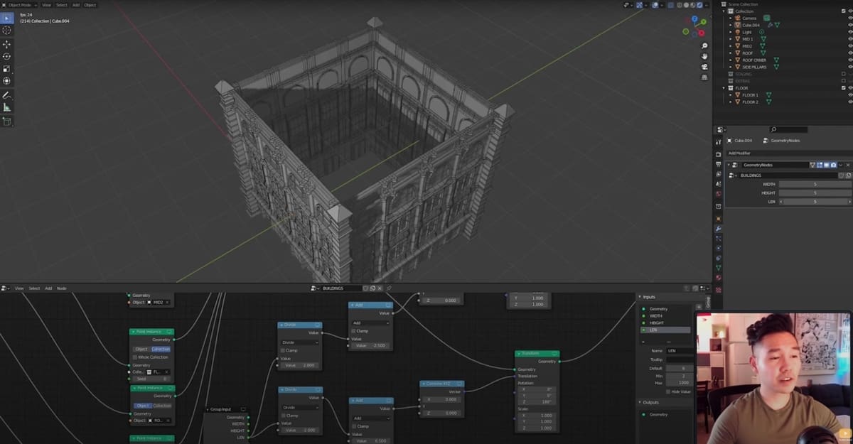
- Architectural design: Geometry nodes can also be used for architectural visualization. Using a node-based system will help create and scale each object and even the entire scene. Later, if you wish to alter any variable, such as the number of floors on a building or to randomize the window pattern, you can do it in a breeze. Vector nodes as well as the Transform and Math nodes come in handy in such modifications.

How to Get Started
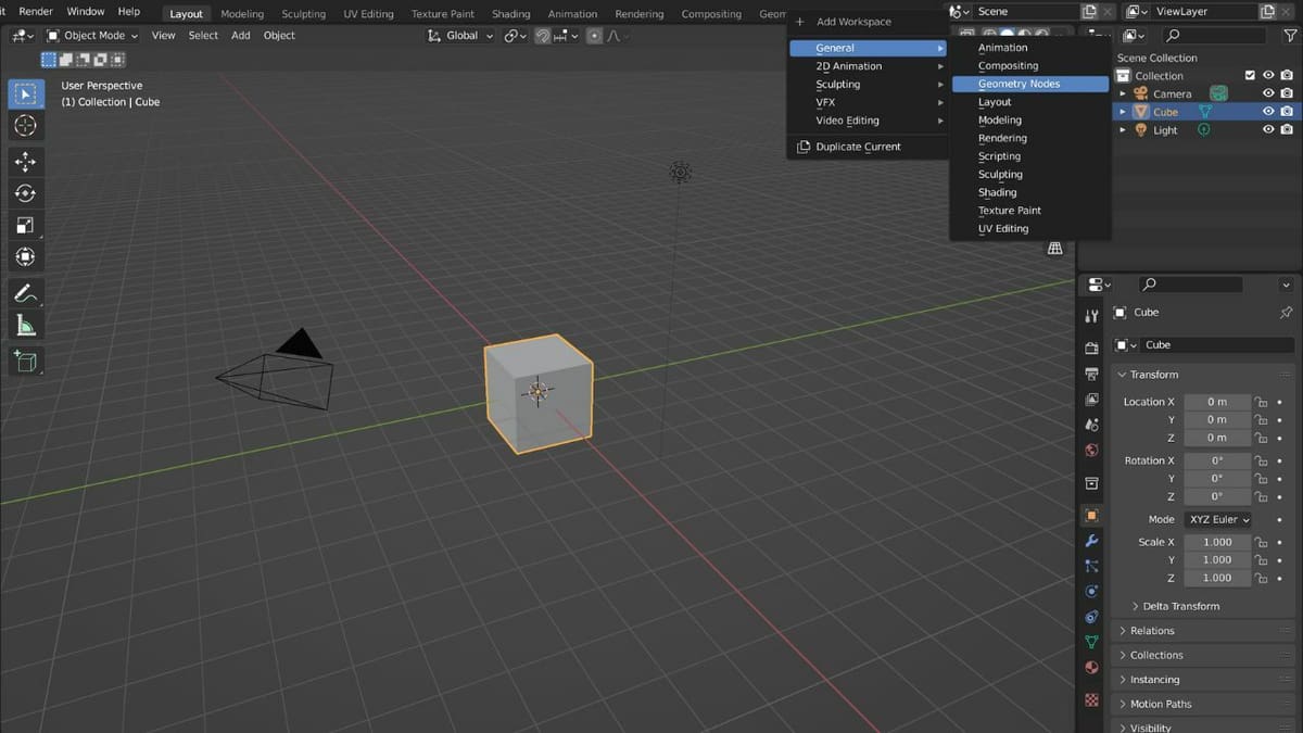
Now that you know more about how geometry nodes work, let’s walk through how you can get started with using them. You first need to add a separate workspace:
- Click on the plus (‘+’) icon on the Topbar.
- Select “General”, then “Geometry Nodes”.
In addition to the 3D Viewport, you’ll see that the workspace now includes the Geometry Nodes editor on the bottom and the Spreadsheet editor on the left. The Spreadsheet editor is used to explore and fine-tune geometry data. You can simply remove it, as we won’t be using this now.
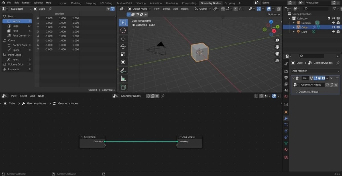
You’ll notice that in the Properties editor on the lower right, the Geometry Nodes modifier is automatically added to the Modifier Properties tab (the wrench icon). If it hasn’t been added, you can simply press the “+ New” button at the top of the Geometry Nodes editor.
In the header of the Geometry Nodes editor, you can find a few dropdown menus. In the middle of the header, you can add a new geometry node group and switch between multiple groups. The Add menu allows you to add all of the different types of nodes, but you can also use the shortcut “Shift + A” to do the same. The Node menu gives various operations related to nodes such as Delete, Duplicate, Copy, Paste, and the like.
Adding Nodes
Once you add a new geometry node group, two nodes appear in the Geometry Node editor: Group Input and Group Output. These two primary nodes illustrate the flow of data in and out of the group. Between these nodes, we can add various nodes to manipulate the object. So, let’s do exactly that.
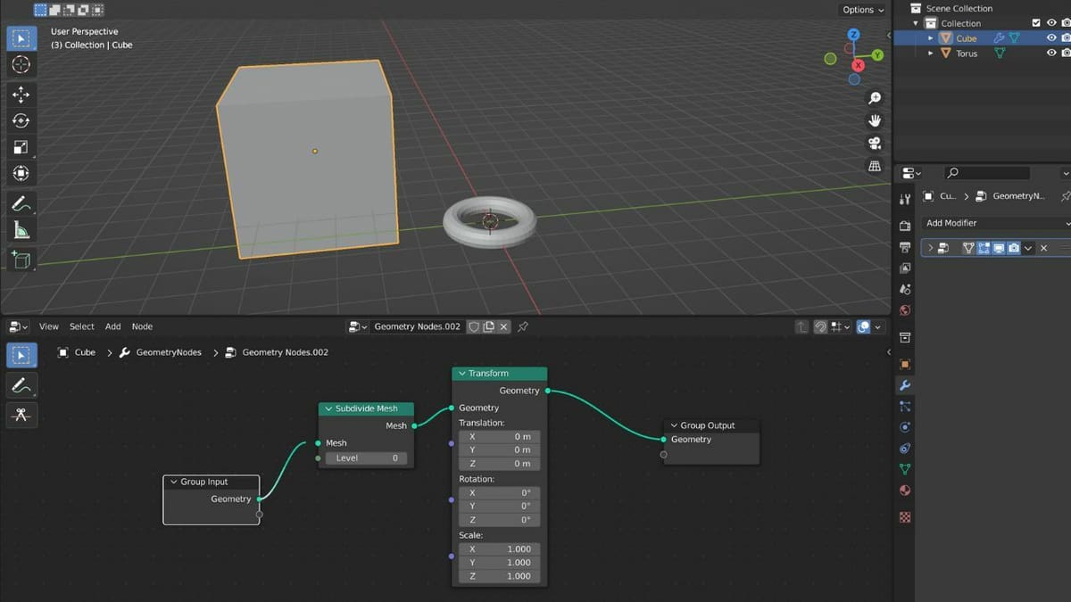
Let’s play with some basic transformations, namely translation, rotation, and scale. To do this, we’ll need to add the Transform node:
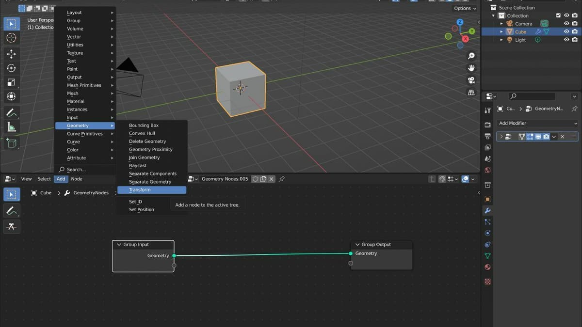
- Click on the Add menu on the header of the Geometry Nodes editor.
- Click the Geometry submenu, then select “Transform”. Alternatively, you could simply search for “Transform” with the search bar at the bottom of the Add menu.
- Place the Transform node between the Group Input and Group Output nodes. The links will automatically connect to the appropriate sockets.
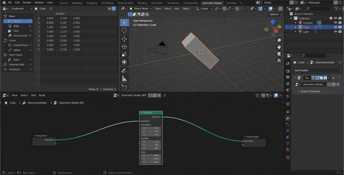
Congrats, you’ve now added your first node!
To experiment with the capabilities of the Transform node, simply change any values in the node to modify the cube. We recommend that you experiment with other nodes in a similar fashion. This will help you become more familiar with everything that’s possible with the geometry nodes system.
If you get carried away and want to delete a node, select the node and press ‘X’ on your keyboard. Alternatively, you can select the node, click the Node menu in the header, then select “Delete”.
It’s also simple to link and unlink nodes. Click and hold on one of the ends of the wire and drag it to the desired node you want to connect to.
Next Steps
We’ve barely scratched the surface of all that’s possible with geometry nodes in Blender. Fortunately, there’s a lot of official and community support to help you improve your geometry nodes game. Blender’s user manual is always a good starting point, and there’s extensive documentation about the software’s geometry nodes features, including explanations of each of the nodes.
Besides Blender’s official documentation, make sure to use sources such as YouTube, Reddit, or other Blender-related forums. The following are a few YouTube playlists that will give you a head start in working with geometry nodes:
- Surfaced Studio’s three-part series on geometry nodes
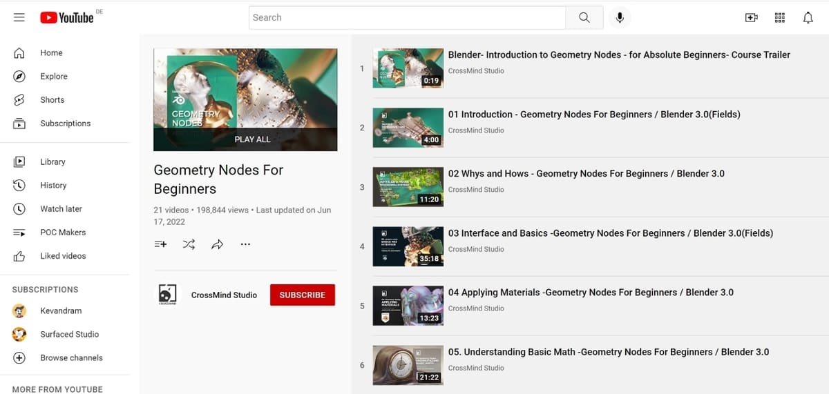
- CrossMind Studio’s Geometry Nodes For Beginners (21 videos)
- Erindale’s videos demonstrating various effects achieved with geometry nodes (30 videos)
And lastly, keep practicing! Learning how to use geometry nodes is like learning how to ride a bike. It may seem overwhelming at first, but it’ll become easier and more intuitive with more practice.
License: The text of "Blender: Geometry Nodes – Simply Explained" by All3DP is licensed under a Creative Commons Attribution 4.0 International License.