10 Instructables Projects that Blew Our Minds

Autodesk Instructables has endless projects and tutorials for all levels. Check out the coolest Instructables projects out there!
Autodesk Instructables is a repository for makers in all sorts of disciplines. It started in 2005 with the staff of Squid Labs, an engineering company founded by MIT graduates. In 2011, Autodesk acquired the Instructables site, attracting a huge and diverse community of makers.
The site houses a diverse range of topics and caters to all experience levels, from kid-friendly projects to advanced robotics. Not only are incredible projects and ideas shared, but each one is also explained step-by-step, many with detailed photos and videos for visual aid.
The site also hosts contests throughout the year in different categories, encouraging the community to create and showcase their projects on Instructables, enriching the site’s content. Very bright and impressive projects have come out of Instructable’s contests.
In this article, we highlight 10 mind-blowing projects shared and explained on Autodesk Instructables to inspire and guide you through the wonderland of DIY culture.
Rubik's Cube Solver
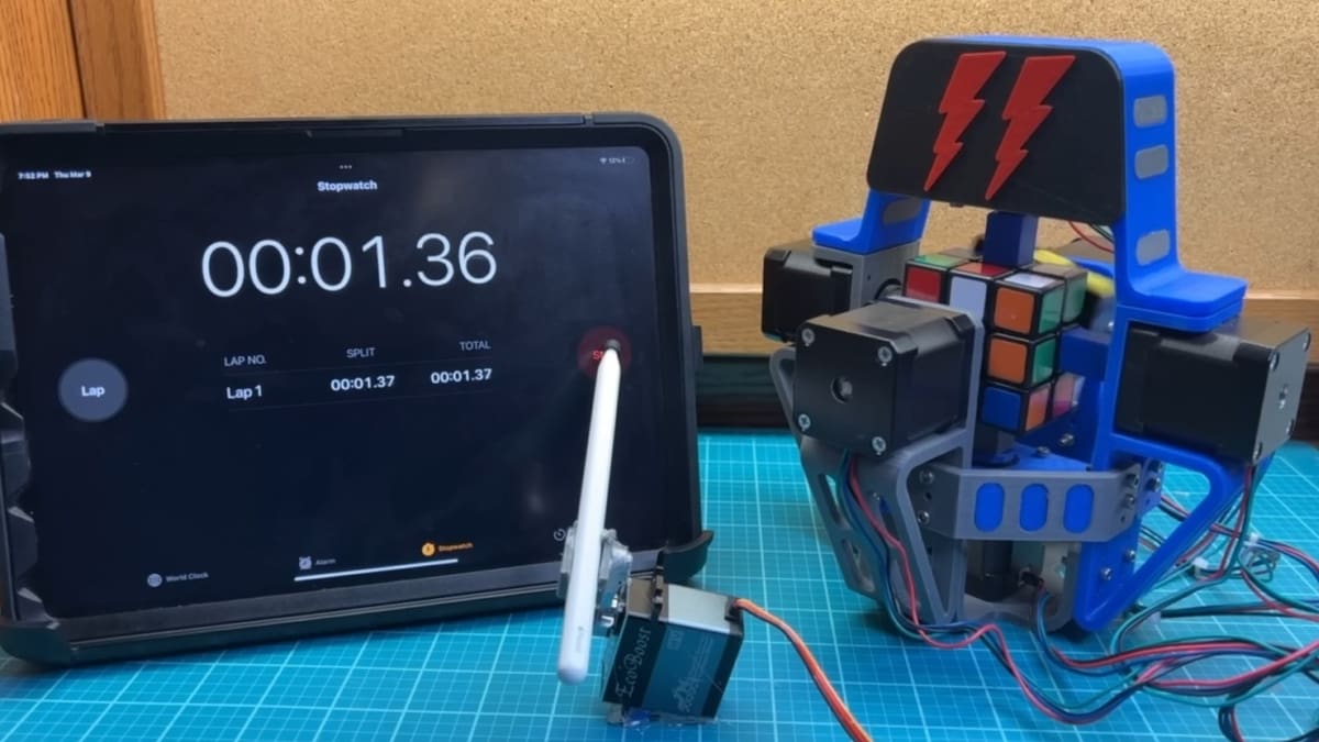
The 3×3 Rubik’s Cube, known as the “Magic Cube”, has always fascinated and intrigued people since its origin 50 years ago. Every year, the World Cube Association hosts speedcubing competitions worldwide. In these competitions, people solve the cube in seconds, with 3.13 seconds being the current world record for the 3×3 Rubik’s Cube. The world record for a machine is 0.38 seconds. In this Instructable, the design for a version of a Rubik’s Cube Solver Machine is explained, giving you the ability to make one for yourself!
Aaed Musa‘s project is composed of the machine itself (including mechanical and electronic components plus the structure to support all of it), an algorithm to solve the cube, and an interface of communication between the initial configuration of the cube, the solver algorithm, and the stepper motor drivers. The machine was designed in Fusion 360 software and its structure is composed of 47 3D-printed parts and 6 stepper motors to rotate each of the cube’s faces.
A Teensy microcontroller is the brain of this bot that solves the algorithm and controls the drivers. The Teensy Ethernet kit is another critical component used to establish a web server for communication between the user interface, “Rubik’s Cube Central”, and the machine. In the Central, the user can set the initial configuration of the cube, that is, the position of each tile, and start the solving algorithm.
After the Instructables project, Aaed designed an updated version of it that can be found on YouTube, built using brushless motors instead of stepper motors to maximize speed. It also features an automatic detection system with cameras to recognize the initial configuration of the cube. Another Instructable project that’s similar to this one is the CUBOTino Pocket, a machine to solve 2×2 Rubik’s Cubes.
- Approximate cost: ~$400
- Skills needed: Rubik’s cube theory, basic electronics, 3D printing, basic web server creation, 3D modeling in Fusion 360, robot assembly, C++ programming in Arduino IDE
- Core components: 3×3 Rubik’s cube, Teensy 4.1 microcontroller, Ethernet kit, stepper motors, 3D printed parts
Magic Mirror
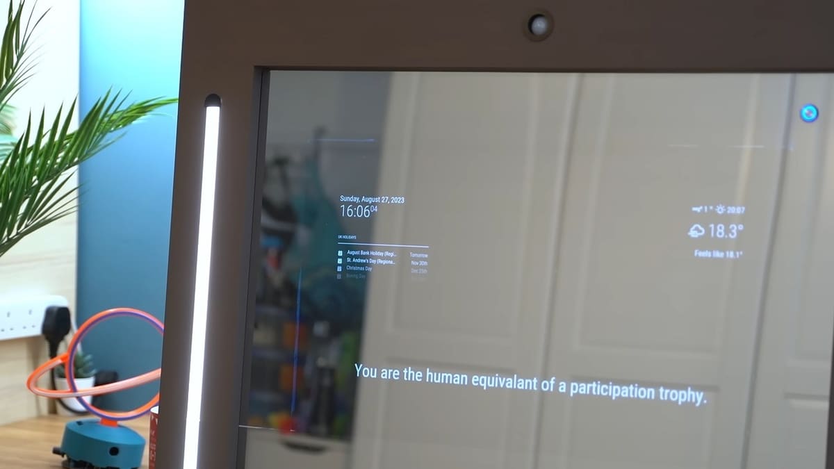
A Magic or Smart Mirror is a mirror imbedded with technology that allows you to see not only your reflection on its surface but also information about the date, weather, news, and other important data for your routine. Using a monitor or a television screen, a mirror, a Raspberry Pi, and structural components, this Instructable guides you through building your own personalized Magic Mirror.
Creator DIY Machines‘ Magic Mirror comprises a front frame and a rear frame structure made of pine wood. If you want to create a project with different mirror or frame sizes, there’s a Wood Cutting Calculator to adjust your desired widths and heights proportionally.
For this project, it’s possible to use a regular glass mirror, but DIY Machines suggests using a two-way mirror film applied over an acrylic sheet. Behind the reflective surface, the screen or monitor gets mounted. When looking at the setup from the side, it appears completely reflective, as a mirror should be. But when viewed straight on, the screen display becomes visible from behind the mirror surface.
The Raspberry Pi can be programmed with the Magic Mirror Software developed by the creator, which is available on the DIY Machines site. However, there are other open-source magic mirror software for Raspberry Pi available on the internet for free, such as the MagicMirror Builders. Another bright idea presented in this Instructable is the installation of a PIR sensor in the mirror, so the monitor only turns on if the sensor detects a person in front of the mirror.
- Total cost: ~$600
- Skills needed: Wood cutting, basic electronics, 3D printing, programming in Raspberry Pi OS
- Core components: Wood, television screen or monitor, Raspberry Pi, mirror or acrylic sheet, 3D printed parts
Solar Tracker
Installation of solar panels as a complementary or primary source of electricity has become very popular in recent years and saw a boom in the US during the Covid-19 pandemic for various reasons. When installed on roofs or metallic structures on the ground, they get positioned at a specific angle (the tilting angle) that allows the most rays of light to reach their surface during sunlight hours. How much more energy could be gained if the panels could change their angle according to the sun’s movement?
That brings us to the purpose of this Instructable: To build a prototype of an affordable device that can support a solar panel and track the sun’s movement in the sky! Solar trackers already exist nowadays, but the main market and application for them is in solar farms. Here, a mechanism named Agile Eye is used to track the sun, and it allows for angular movement of objects in 2 or 3 axles of rotation due to the use of 2 or 3 revolute joints, respectively. The movements it’s able to reproduce are compared with human eye movements.
The general concept of the project is that four photodiode sensors are placed 90° to each other, and their drivers read the luminosity in each direction. Down the line, the Arduino program compares the intensities and directs the stepper motors to rotate the Agile Eye mechanism to the highest intensity light. The prototype structure was made from MDF, and the components of the Agile Eye mechanism were 3D printed in PLA.
The team that designed the solar tracker was composed of six master and undergraduate students! They’ve made available all the files, among them the Arduino program.
- Total cost: ~$120
- Skills needed: 3D printing, mechanical assembly, C++ programming in Arduino IDE, 3D modeling in Inventor, laser cutting, basic electronics
- Core components: MDF, Arduino Uno, stepper motors, photodiode sensors
Weather Station
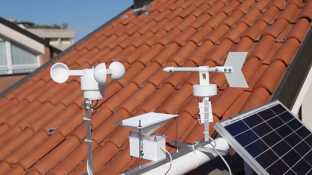
Weather stations are a set of various sensors that measure in real-time climate parameters such as wind speed, amount of precipitation, temperature, atmospheric pressure, and more. By storing and analyzing this data, it’s even possible to make weather forecasts. Personal weather stations have been gaining popularity as a way to document weather patterns specific to your own backyard. This Instructable walks you through the process of building a personal weather station from scratch!
Giovanni‘s DIY weather station is composed of a temperature sensor, a wind vane, an anemometer, a rain gauge, and a pressure sensor. Each sensor gets connected to an Esp32 microcontroller, and the data is set to a Home Assistant app through a Wi-Fi connection. The housing for the sensors and gauges was designed in Tinkercad and 3D printed, then attached to an aluminum structure.
The temperature sensor used was the DHT22 sensor, which is housed in a 3D printed Stevenson screen. This kind of gauge protects the sensor from weather conditions but allows the airflow to reach the sensor. The wind vane detects the wind direction with four Hall effect sensors, one for each cardinal point. The anemometer uses almost the same principle to measure the wind speed, where the 3D-printed half-spheric bowls rotate a magnet and a stationary Hall effect sensor records the rotation speed.
Assembly of the rain gauge has a dedicated Instructable. The device funnels rain into a central collection cup. This cup can only hold a certain amount of water before it dumps it out into the reservoir. All the internal components need to do in order to calculate how much rain has passed through is count the number of times the cup dumps out the water.
All these components together make quite a comprehensive personal weather device and a great project to try out for those who are looking to gain experience in sensors and wiring.
- Total cost: ~$270
- Skills needed: 3D printing, basic electronics, soldering, mechanical assembly, 3D modeling in Tinkercad, ESPHome programming, Bynk or Home Assistant
- Core components: Esp32, DHT22 temperature sensor, Hall effect sensors, BMP180 atmospheric pressure sensor, 3D printed parts
Modular Macro Keyboard System
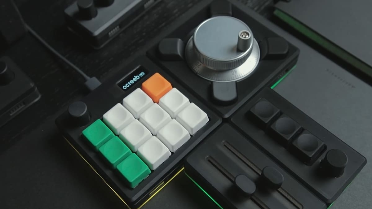
Alternative input devices, also known as macro keyboards or macro pads, are all about making your work more productive. While they won’t replace your entire keyboard and mouse, you can program them with macros to perform a specific series of tasks with just the push of a button. They are commonly used in video and photo editing, color corrections, music production, and other works to control media and can consist of any combination of dials, keys, and sliders.
The creator guides you through the challenge of making your own personalized macro keyboard in this Instructable! The project was inspired by the Monogram Creative Console and also takes a modular approach, giving you the ability to connect various module types magnetically into the exact configuration you need for the moment.
A major part of this project is the keypad, the build for which is featured in a dedicated Instructable by the same creator. It involves a custom printed circuit board (PCB), named Ocreeb MK2, for which you can find the files on GitHub. Additional components include a module with sliders, a module with switches, a module with dials, and a module with a CNC encoder. All the enclosures were designed in Fusion 360 and 3D printed with resin.
- Total cost: ~$150 per module
- Skills needed: Soldering, electronics, KMK firmware programming in CircuitPython, 3D printing, 3D modeling in Fusion 360, mechanical assembly, Adafruit seesaw firmware
- Core components: RP2040 microcontroller, custom PCB, Adafuit seesaw framework, 3D printed parts
Nature Trail Mapper
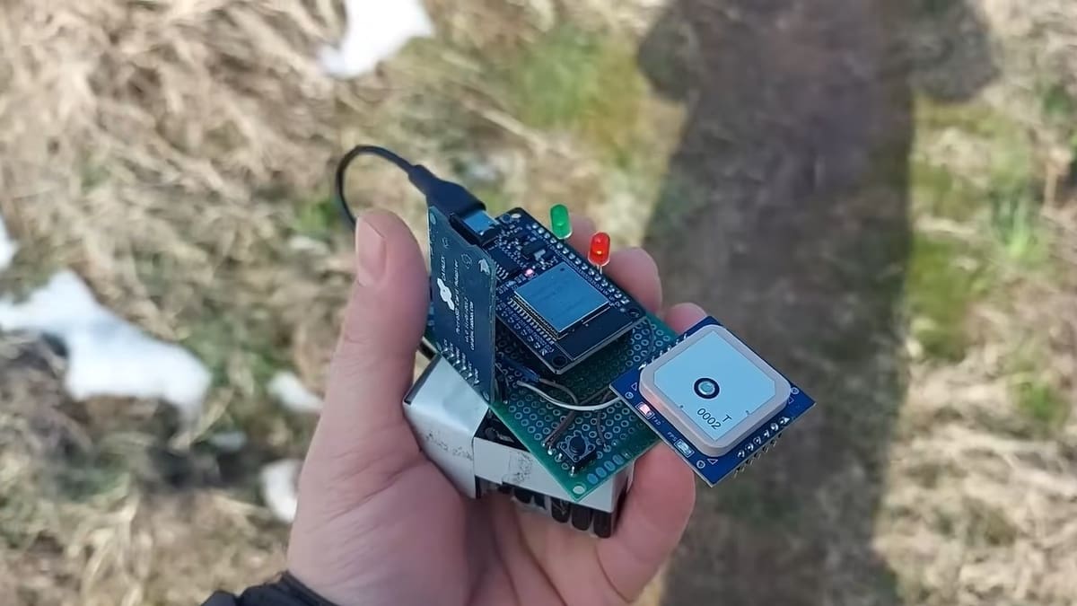
Satellite navigation works with radio signals, independent of internet connection. It can estimate the geolocation of a navigation device, sometimes with an accuracy of a few centimeters. The information can later be used to track or log paths for navigation. This Instructable teaches you how to make a homemade navigation device prototype that tracks and stores your outdoor hiking paths!
The project is based on an Esp32 microcontroller, and the project’s creator Taste the Code has made the complete code available online. The core of the navigation device is the RYS352A GNSS module that can work with all the global navigation systems, including GPS. The GPS signal works best outdoors, so an LED connected to the ESP32 will indicate that the GNSS is functioning.
To store the data, a MicroSD module was used with a switch or a pin button to start the recording. Another LED was installed to indicate that the device is recording the geolocation data in KML extension files, which can be opened in the Google Earth application.
- Total cost: ~$140
- Skills needed: Soldering, basic electronics, C++ programming in Arduino IDE
- Core components: Esp32, GPS module
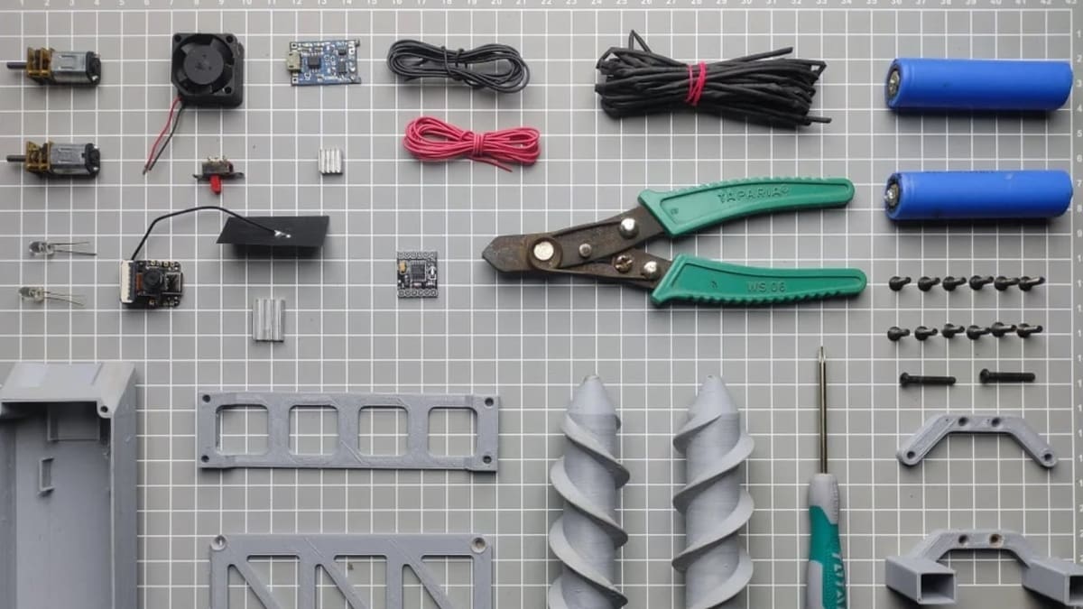
All Terrain Robot
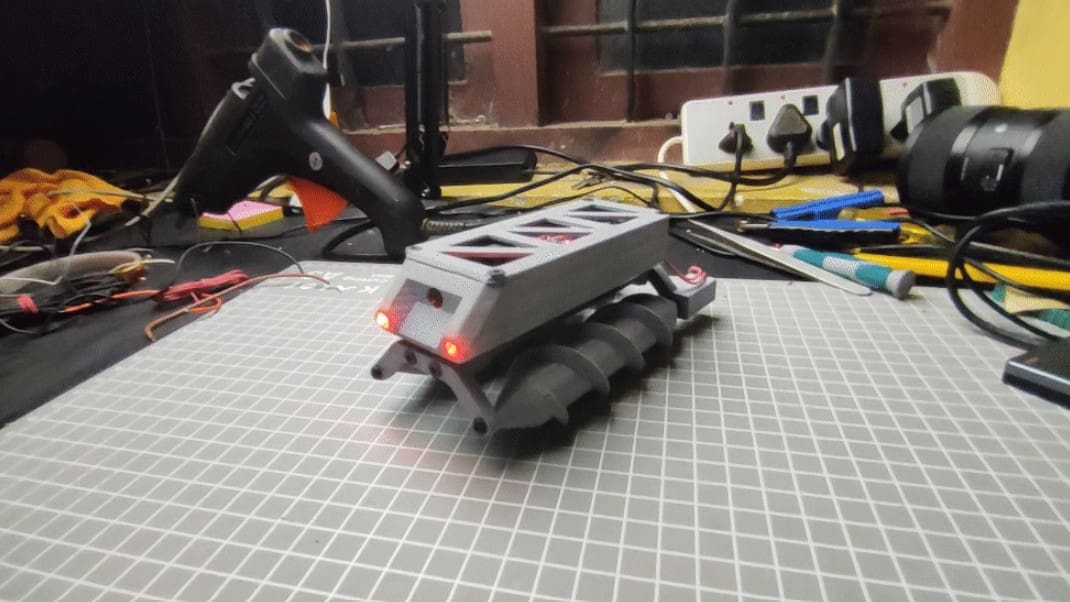
A screw-propelled vehicle uses a system of two screws, one rotating clockwise, and the other rotating counterclockwise, to perform a linear movement in unfavorable terrain conditions. Although it can move on flat ground, it operates better when riding in mediums such as mud, ice, sand, and soil. This Instructable helps you to build a screw-propelled robot controlled by your smartphone!
The robot body was designed in Fusion 360, and most of its parts were 3D printed. The robot is programmed with a Seeed Studio Xiao Esp32S3 microcontroller, which has a built-in camera to help you navigate from your smartphone via Wi-Fi connection. Screws that allow the movement of the bot over the harshest terrain are driven by two DC motors. Building one of these unique robots is accessible to novice makers, thanks to the complete code (developed in Arduino IDE) being available on the project page.
- Total cost: ~$110
- Skills needed: 3D printing, 3D modeling in Fusion 360, basic electronics, mechanical assembly, C++ programming in Arduino IDE
- Core components: Esp32S3, GA12-N20 gear motors, 3D printed parts
Electric Kayak
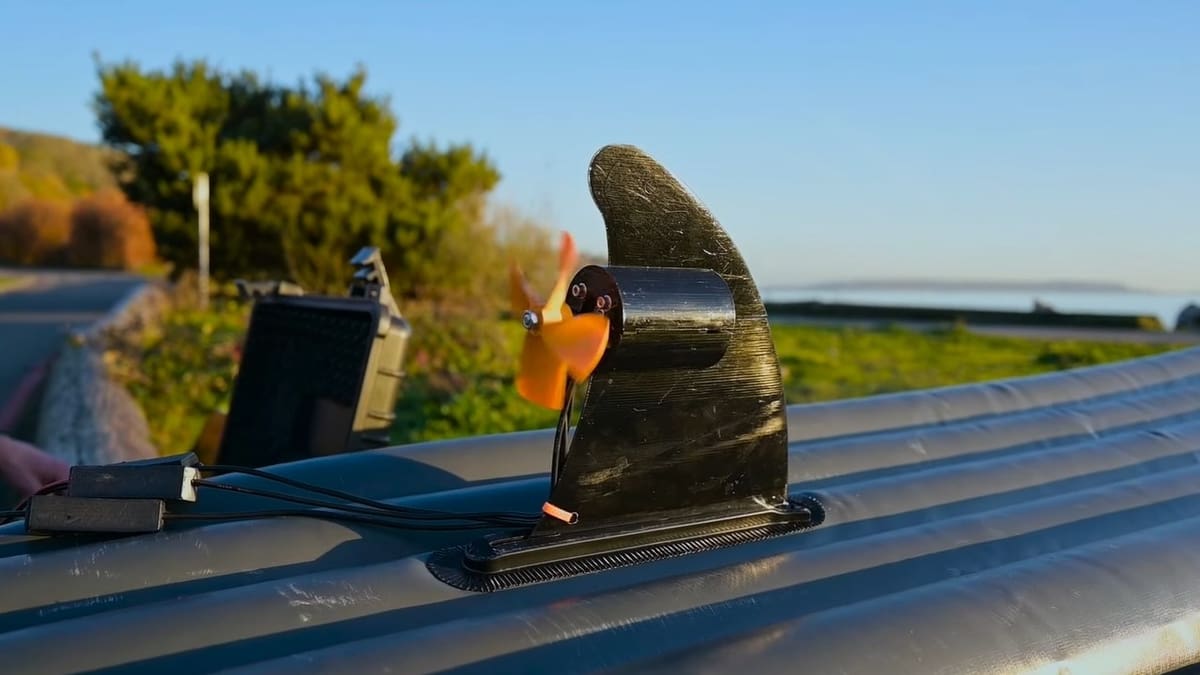
The kayak was first designed by the people of the Arctic North about 5,000 years ago as a way of navigating cold waters for hunting and fishing. The movement is traditionally driven using kayak paddles and plenty of arm strength. However, in the last years, a new kind of kayak propulsion was introduced to the market: the electric kayak. In this Instructable, you’ll learn how to upgrade your kayak and say goodbye to your old paddles!
Besides the inflatable kayak, the core of this project is a waterproof 160-kV motor and a VESC motor controller. A new fin was designed in Fusion 360 to house the motor and later 3D printed. All the other electric components, including the battery, were stored in a case that could be put inside the kayak.
To complete the project, the speed of the motor needs to be tuned using VESC tool software. The creator found that a speed of 4.2 MPH worked well with one person in the kayak, but it’s up to you to tune it to your conditions.
- Total cost: ~$640 (less if you already have a kyack)
- Skills needed: 3D printing, 3D modeling in Fusion 360, basic electronics, mechanical assembly, VESC Tool
- Core components: Inflatable kayak, waterproof 160-kV motors, VESC motor controller, 3D printed parts
Sand Table
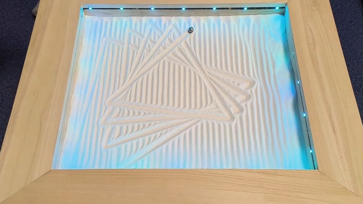
A sand table, also known as the zen garden, is a rectangular or square box that holds a layer of sand. It normally comes with decorative stones and miniature gardening forks to create patterns in the sand, which is quite a calming activity. This Instructable builds an automatic sand table that draws patterns in the sand by itself!
The project consists of a ball bearing commanded by magnetics, which in turn are controlled by an Arduino microcontroller. As the magnetics moves underneath the sand pit using timing belts, the ball bearing rolls in the sand, leaving mesmerizing patterns behind. The speed of the ball, the pattern it makes, and the LED colors of the table can be adjusted with a remote control.
To build one of these, the creator details how they designed a new baseboard for the coffee table that can hold rails, bearings, timing belts and their stepper motors, plus a magnet. All the patterns used in the Arduino code were designed using Sandify, a site where you can create new patterns and export a CNC-compatible code of the motions.
- Total cost: ~$200
- Skills needed: Laser cutting, basic electronics, mechanical assembly, C++ programming in Arduino IDE
- Core components: Table, Arduino Uno, sand, timing belts, stepper motors, magnets
Cosmic Clock
Sky observation has always fascinated humankind. The universe represents mystery, and humanity has always sought answers about our existence by looking up at the sky. This behavior has helped us log the passage of time in the early eras of our civilization, eventually leading to the creation of calendars and clocks. Now, you can return to tracking celestial bodies in the sky with this cosmic clock Instructable!
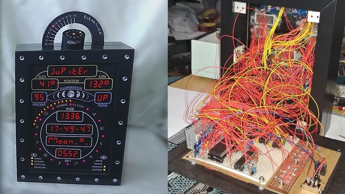
This invention, named the “Cosmic Clock”, helps you track celestial bodies in the sky by displaying a real-time clock and other information like the current date, temperature, and atmospheric pressure. Additionally, it brings astronomic information such as the approximate date of the next meteor shower, the Moon’s illumination percentage and phase, the visibility of planets in the sky, and the azimuth and elevation angle of the sun, moon, and each solar system planet.
The clock’s main structure is made of two photo frames and a PVC sheet. The major information is displayed with 7-segment displays, while secondary visual information is displayed with LEDs. Information about the sun, moon, and each planet is displayed cyclically for about 4 seconds each in the original program.
No internet connection is needed in this project. All the astronomic information is calculated by the ATMega644 microcontroller using the Arduino program shared on its Instructable page. For time display modes with LEDs, the ATMega328 was used.
- Total cost: ~$400
- Skills needed: Machining and hand tool experience, electronics, mechanical assembly, C++ programming in Arduino IDE
- Core components: DS3231 real-time clock, DS18B20 temperature sensor, ATMega644 and ATMega328 microcontrollers, LED displays
License: The text of "10 Instructables Projects that Blew Our Minds" by All3DP is licensed under a Creative Commons Attribution 4.0 International License.