3D Printed Molds Tutorial: How to DIY Your Own

Using your 3D printer to create molds is not only possible but easy. Check out our simple guide on how to make 3D printed molds yourself!
Molding is a process that’s widely used in manufacturing. Molds enable parts to be reproduced in a variety of materials and can be used to make a whole range of things. They’re usually quite expensive to get made, though. So, there’s a great cost benefit in being able to 3D print your own.
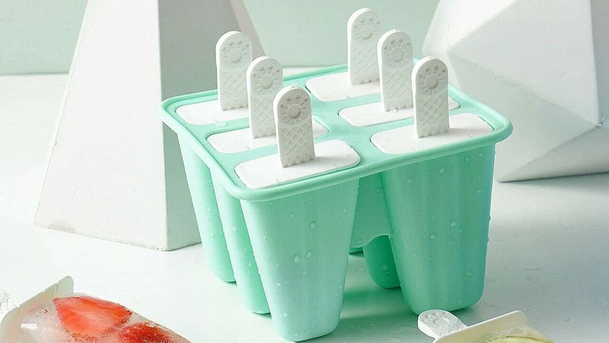
A mold is essentially a cavity into which materials are injected. If you’ve ever made popsicles at home, it’s a similar process. With 3D printing, you can print the mold, then fill it with a material of your choice. After it dries, you open up the mold to reveal your final part.
In this article, we’ll get into the nitty-gritty of 3D printed molds and walk you through the process of making your own. There are different ways of casting parts, but we’re going to focus on casting with two-part materials with a two-part mold that can be reused. Two-part materials are used extensively in manufacturing, and they solidify only when the two individual parts are mixed together in certain proportions.
Integrating 3D printing into molding does require a little more work and some extra equipment than standard 3D printing projects. However, we promise it’s totally worth it! Let’s dive in!
The Basics
3D printed molds have all the same characteristics as a standard mold, except you can make it at home with a bit of work. There are lots of molding techniques, but most of them require specific machinery to put into practice. Most people will be familar with injection molding, which is a process where molten plastic is forcefully injected into a cavity before being ejected from the machine.
The process of casting parts is somewhat similar – only the mold is plastic or rubber, and the material is poured into the mold without the application of any additional pressure. Casting can also involve an additional process in which the mold is put in a vacuum chamber to remove any air trapped inside. It’s not necessary for every design, however.
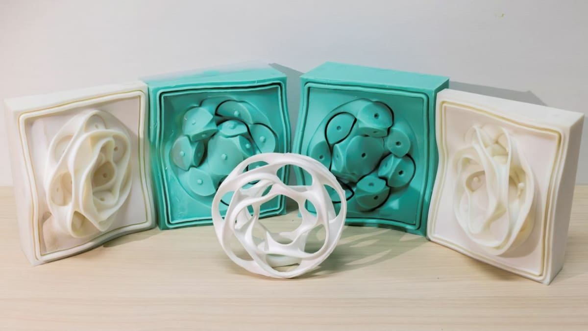
There are two main methods to create 3D printed molds. You’ll either print the mold directly and pour in a softer material, or you’ll print the part and pour a softer material around it to create a silicone mold. With the latter method, a box – out of foam board or another material – will need to be built around the printed part so you can pour the silicone into it.
3D printing molds is accessible to anyone who wants to try it, but it’s especially helpful if you’re looking to get any of the following from your 3D printing experience:
- Exact copies: If you need consistent replication on a mass scale, 3D printing molds will keep your designs identical without any need to recalibrate between batches. Although the quality of hobby 3D printers is improving, when you 3D print a mold, you only have to worry about the design details once. After that, you just reproduce the same part over and over again as needed.
- Starting your own small-scale manufacturing business: If you’re looking to get a one-stop manufacturing business off the ground on a (relatively) shoestring budget, 3D printing your own molds will help you go far. Start-up costs can make or break a new business, and there are great 3D printers available for much cheaper than standard manufacturing equipment. Printing your molds allows you to start small, keeping start-up costs down.
- Everything all at once: Although you do have to create one mold at a time, once you’ve got your set ready, you can use them all at once and produce your objects in batches. This will speed up your production and leave your printers free for more complex objects.
Pros & Cons
Pros
We’ve covered a lot of reasons why 3D printing molds is a simple way to upgrade your manufacturing game. Here are the biggest pros to giving it permanent room in your 3D printing toolbox:
- Much lower price point for low-level batch manufacturing: Depending on the 3D printer you decide to buy, you can get started with 3D printed molds for about $200. Compare that to an average of about $10,000 for entry into industrial manufacturing, and it’s easy to see how 3D printed molds are making manufacturing accessible to people who could never afford it before.
- No specialty materials needed: You can start right away if you’re already into general 3D printing. For most two-part materials, you can use molds printed in standard printing resins and filaments. You only need special materials or equipment if you want to pour hot materials or do “lost-print” casting.
- Easy to tweak your designs: Making a standard manufacturing mold is a multifaceted process that doesn’t allow for easy change once you’ve completed the final version. But 3D printing your mold gives you more design leeway. If you notice a change you need to make after your first batch, no sweat. Just go to your CAD, tweak it, and 3D print it. No paying extra for new molds, no waiting another month and a half to see if the change worked – you’re already back in business.
- More material opportunities: There are so many two-part materials that can be poured into your 3D printed mold that it gives you the opportunity to make more things with just a desktop 3D printer. It’s a more involved process, but you can repeatedly make nice parts in epoxy or rubber with ease once you have a mold.
Cons
3D printing molds has a few downsides. So, here’s what you need to know before you jump in:
- Not suitable for large manufacturing batches: Although 3D printing molds makes it possible to create a set of objects at the same time, there are size limits to that effectiveness. If you’re looking to directly jump into making batches of 100 or more, you’re going to find your efforts in mold printing more laborious than helpful. That’s the general tipping point where the higher cost of industrial injection molding becomes more feasible when you compare capacity to price point.
- Design limitations: Since your part has to come out of a mold, you lose some of the design freedom you have with 3D printing. Parts can’t have encapsulated features, which we’ll talk more about later. Basically, you can’t just make anything because you have to be able to remove the mold after you’ve poured the material.
- Wear and tear: Since 3D printed DIY molds are typically constructed of less durable material than industrial molds, they’re more likely to be damaged, especially when used regularly. A standard injection mold could be used to make hundreds of thousands of parts, but a 3D printed one can likely make hundreds of parts, depending on the materials used. However, casting a softer material is the best way to reduce wear and tear.
Design Considerations
There are some important design considerations to know about before you design your mold. Here are some rules of thumb and tips for getting the best results.
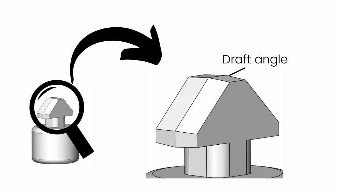
- Draft angles: The design to be cast needs to have a draft angle on its faces so it can be easily removed from the mold. Allow at least 2 degrees of draft angle to ensure the part will come out.
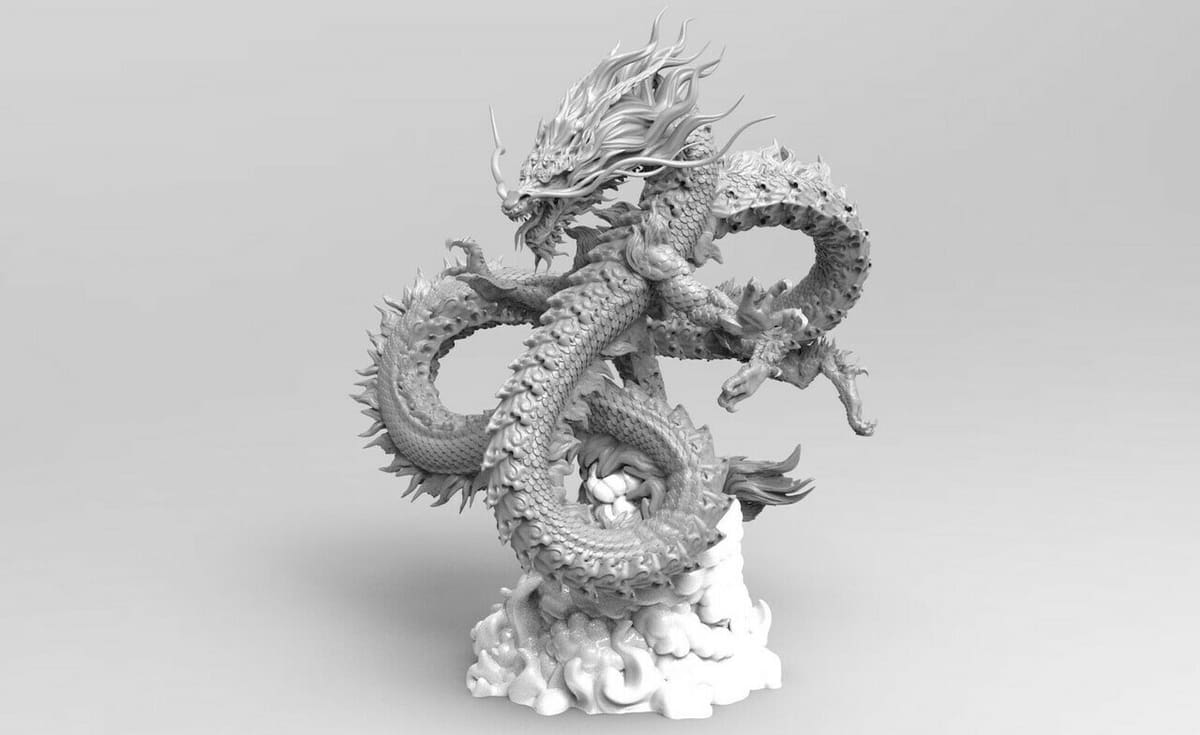
- Encapsulated features: You can’t have encapsulated features in your design. For example, if you’re casting a figurine, the hand would have to be fully open or in a fist but not somewhere in between because this would prevent you from pulling the part out without damaging the mold.
- Air vent: You need to include a way for air to escape the cavity without letting the casting material spill out. We’ll talk more about this later.
- Keying: Use keying to make sure the two halves of the mold always fit together correctly. A key is any shape that fits into another. It can be designed to ensure the faces are always in the correct position and rotation.
- Parting line: Two-part molds are the simplest, but you need to design around the center line that forms where the two halves of the mold join.
- Lifespan: The mold’s lifespan will depend on materials and design. For a long life, print the mold in a very hard substance and plan to cast in a much softer material. You can extend the process to make a rubber mold and cast a hard substance if needed.
Tutorial
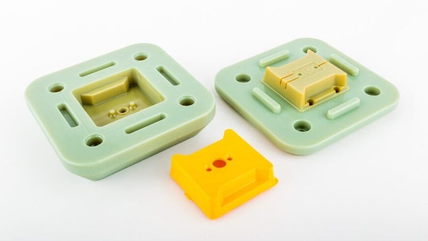
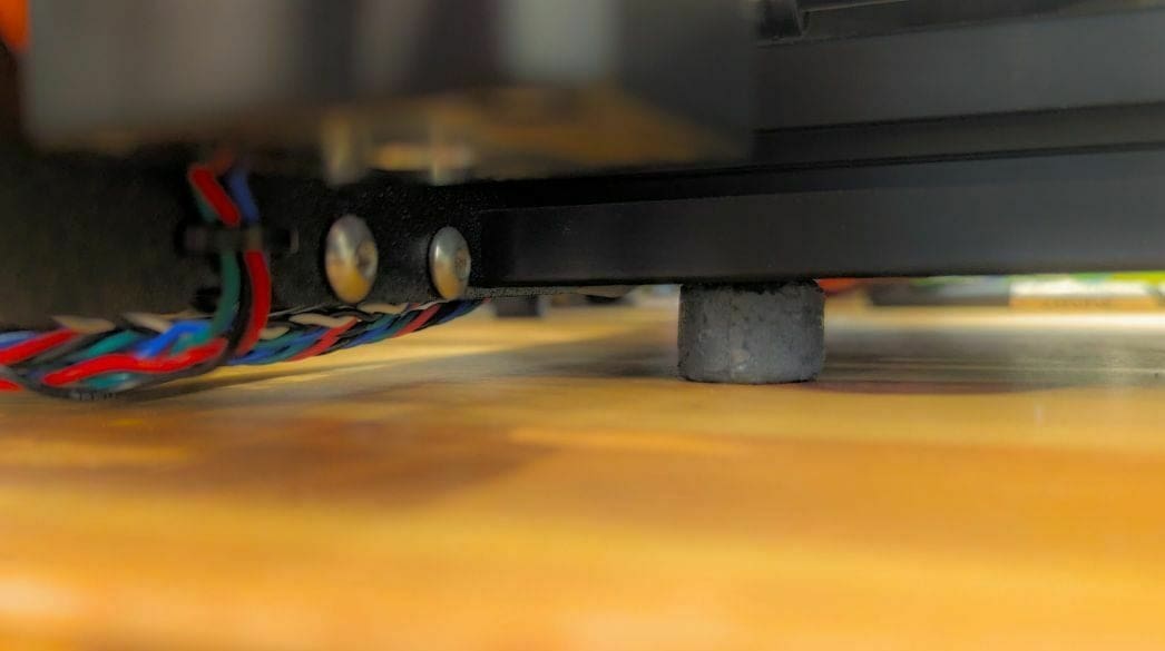
To demonstrate the points we’ve made above, we’re going to create a two-part mold that will let us create new silicone feet for the Prusa MK3. The MK3’s standard legs are a bit too rigid, and we want to try and reduce the noise the machine makes.
The process will begin with designing the part and creating the mold design. Then, we’ll print the mold and cast the final part.
For the first two parts, we’ll be working in SolidWorks and assume you know the basics of the UI and generally how to navigate around the software. If you need an introduction, check out our SolidWorks tutorial for beginners.
However, you can apply the principles we’ll discuss below to any CAD suite. For example, if you’re looking for a free option, many use OpenSCAD for this purpose because you can automate some of the steps.
What You Need

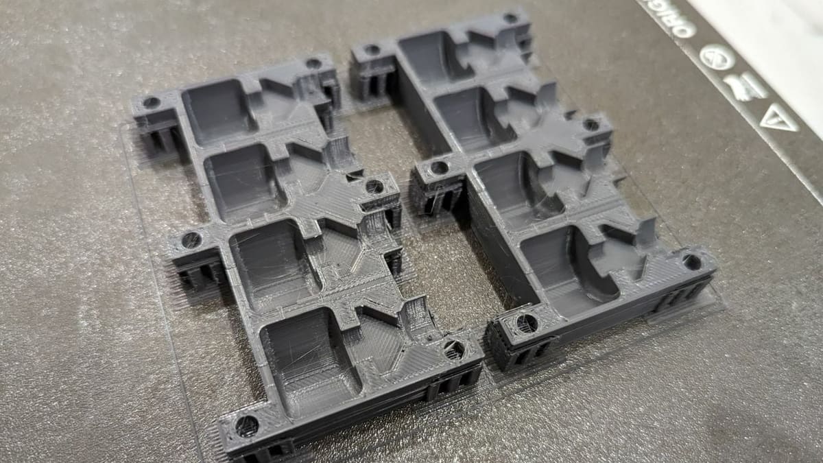
Basically, we’re going to make a mold to cast a urethane rubber part, so the choice of 3D printing materials isn’t that critical because the urethane is so soft. The two-part mold will bolt together for ease of pouring, and we’re going to make it so we produce four feet at a time.
Since the feet are for the Prusa MK3, we’re going to print the mold on that machine. If you want to make high-resolution parts, however, we recommend you use a resin 3D printer for the mold production.
Here’s a list of items you’ll need before getting started:
- A 3D printer, preferably resin
- Gloves and goggles for safety
- Scales for measuring the proportions of parts A and B
- Mold release – This makes it easier to take the part out of the mold and is worth getting if you’re doing a few molds. Slide, for example, allows you to paint the parts if needed.
- Two-part urethane rubber – We’ll be using Simpact 85A from Smooth-On.
- Mixing sticks
- Pigment – This is necessary if you want to color the material. We used UVO colorants for this tutorial.
- Vaseline – This is essential for FDM prints, but if you’re using a resin 3D printer, you won’t need it.
Although we won’t use them in this tutorial, a vacuum chamber and pump will give you the best results.
Part I: Designing the Part
As with most things in manufacturing, this process starts with a design. We’re going to start with the actual form rather than drawing the mold first, as drawing the original form first makes it much easier to create the mold later.
As mentioned above, we’ll be making custom feet for the Prusa MK3. Some find the feet of the Prusa MK3 to be too rigid, so we’re going to create some rubber feet for more silent operation. If you want to skip ahead, you can get the design for the mold on Printables.
About the Design
On the Prusa, the legs slide into a 30-mm aluminum extrusion. On the original part, you’re meant to slide these on before installing the face plate. This can be kind of annoying if the feet ever get knocked off because you have to try and squeeze them into the central channel in the extrusion. So, we’re going to design our part to be easily installed while the Prusa is fully assembled, but we’ll try to keep it similar to the original.
When doing parts like this, it’s really useful to have a vernier caliper on hand to measure the dimensions of the machine or whatever you’re working on. The channel running down the center of the extrusion is 8 mm wide, and the depth before the channel opens up is about 3 mm. The total depth of the channel is about 9 mm, and it has chamfers on both sides. The original feet are 10 mm tall, but we’re going to increase that slightly to 15 mm.
Since we want to reduce the noise resulting from vibration of the machine, we’re going to try and make the legs have a dampening effect on the machine’s motion. We’ll do this through the actual shape of the part by allowing for some flexibility in the component. This is achieved by having a larger barrel section at the bottom of the foot.
Designing for Casting Molds
As mentioned earlier, we’re going to maintain at least 2 degrees of draft on the part so it’s easy to get out of the mold. Our part will be mostly round, so this is easy to achieve, but it’s something to keep in mind for your own designs.
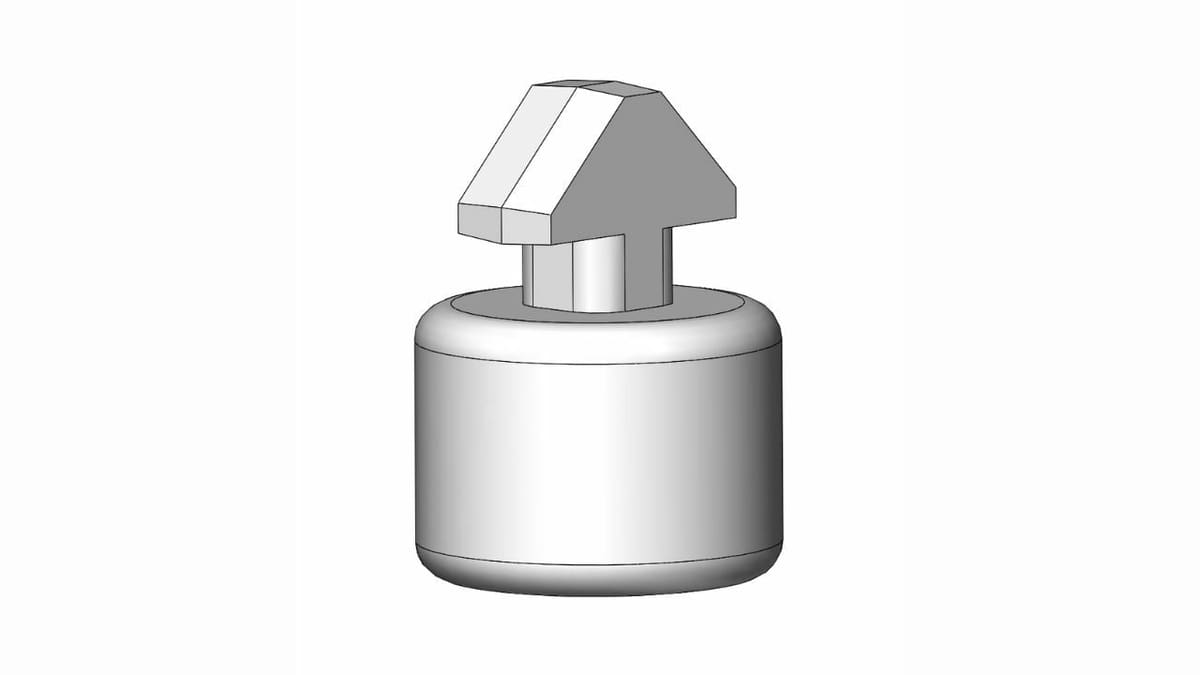
For the sections that can’t be round, we’re going to curve all the edges and keep the faces at a draft angle of 4 degrees. You can see the slopes on the top of the part in the image above. 2 degrees is a minimum, not an objective, so aim for the maximum draft that still keeps your part functional and aesthetically pleasing.
For the main body of the part, we start by drawing a circle and extruding it. For the top section where the part is inserted into the extrusion, we’ve measured the extrusion with a vernier caliper and drawn a T-shaped knuckle that can be rotated into place. The top section has a 4 degree draft angle on the faces where the mold separates so it can lift easily out of each part of the mold.
Part II: Designing the Mold
We’re now going to make the mold based on the part we’ve made.
Step 1
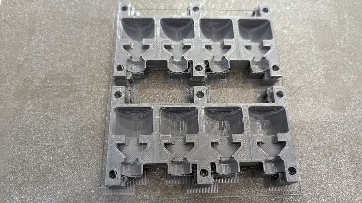
In this step, we’ll draw the mold casing with a spout to pour the urethane into the mold.
- Draw a cube that’s slightly bigger than the component around the original part. However, make sure not to combine the two parts so they remain separate.
- Draw a circle where you would like the spout to be placed, then extrude cut that circle down toward the form within the mold.
- Add a smaller circle at the bottom of this hole, then extrude cut that until it meets the hollow within the mold.
- Chamfer the top edge of the spout so it looks like a funnel and add a circle that can be extruded upwards. This circular part at the top of the mold makes it much easier to pour into it and provides some room for additional material that can sink into the mold as necessary. It’s recommended to include this in your own designs.
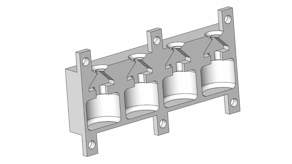
- Duplicate this section so you have four leg molds in one piece.
Step 2
We’ll now create the two halves of the mold. Since the mold is the same on both halves, we’ll just work with one half afterwards.
- Draw a plane where you want to divide the part. Choose the orientation of the plane so that the part can still be removed, and keep in mind that there may be some seeping of material – which is called “flashing” – along this line.
- Divide the block in two. These two sections will be the two halves of the mold, so the division should occur at the point where the draft angles meet.
Step 3
The next step is to add some air outlets to let the urethane fully sink into the cavity. The air outlets need to be designed so that they let the air out but not the urethane – at least at first. The urethane usually won’t creep into very small holes, so this is readily achievable.
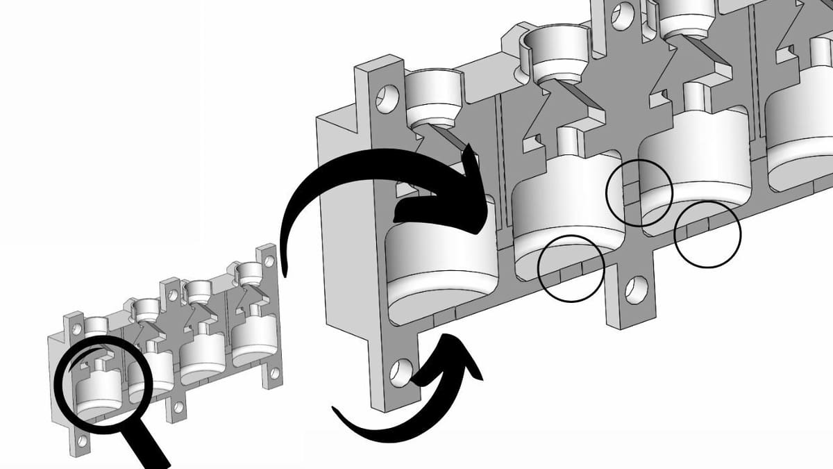
- First, draw a rectangular channel from the bottom and sides of the part that can be cut extruded without interfering with the features of the part. If you’re using a resin printer, you can make these outlets round if you want, but for FDM, it’s best to make them rectangular channels.
- Make each channel 0.2 mm deep using the extrude cut feature. That’s 0.1 mm per half of the mold.
Tips
When designing your own part, put these channels in a position where they’re as short as possible. Also, keep in mind that there might be some extra material cured around this position, so ideally, it should be easy to access with a knife.
Although the channels go straight out the top and bottom in this mold design, you can have them all exit at the top in your design, if possible. This will decrease, or eliminate altogether, the amount of seeping when pouring low-viscosity materials.
If you’re replicating this design, you may get some seeping around the air outlets when you first pour the urethane and once it starts to cure, depnding on the viscosity of your material. The mold will be filled, though, so don’t worry about it.
Step 4
To finalize our mold, we’ll add some keying to the design and a way to hold the two parts together in one step. If you’re using a very precise resin printer, you can put some extrudes on the face of one half of the mold and put matching extrude cuts on the other half so they line up nicely.
In this design, we’re going to use the bolt holes as the keying. Since our mold halves are symmetrical, we’ll just work on one half, then print two of them later.
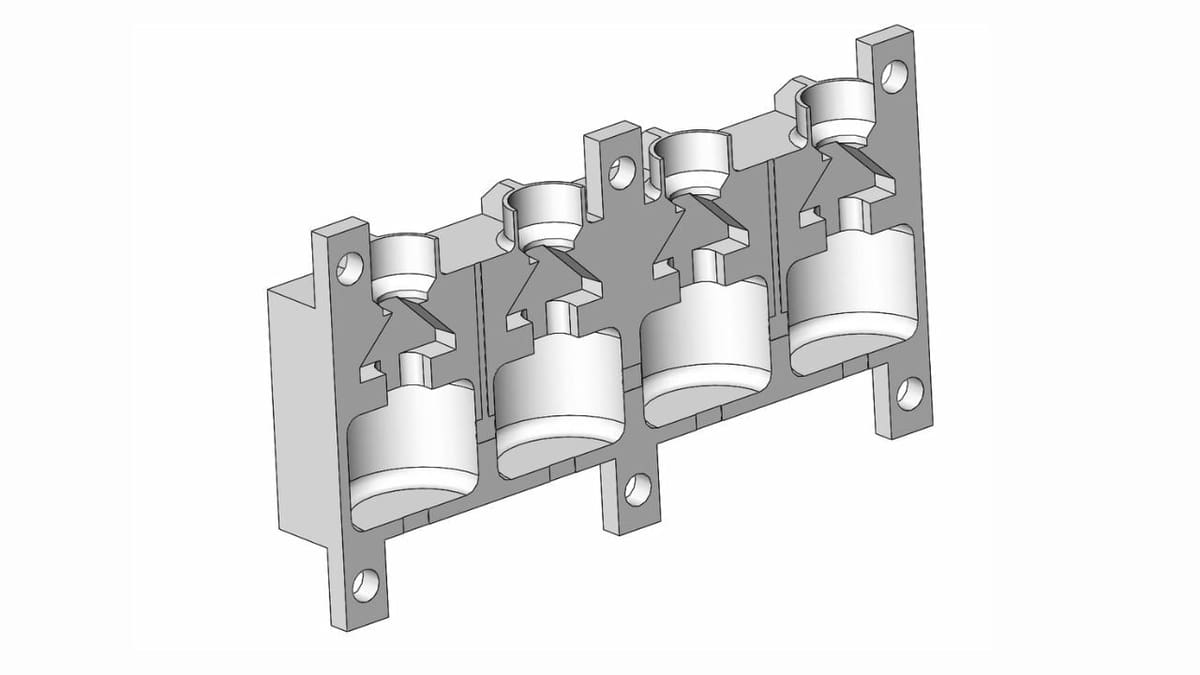
- For the bolt mounts, draw a rectangle at each corner of the mold half as well as the center point at the top and bottom of the mold half.
- Extrude this drawing and add a hole for the bolt to pass through. The hole should be a snug fit so that it can also perform the keying. If you have the bolts on hand, measure the thread section with your vernier caliper.
That’s it for the mold section of this tutorial. These principles apply to any object you want to make a mold from, so you should be able to give it a go now.
Tip
Before we move on to printing the mold, it’s worth mentioning that some parts won’t enable you to add air outlets depending on what kind of mold you’re making. It’s usually not an issue if you’re 3D printing the mold, but it’s worth knowing that you can use a vacuum chamber to remove any air from the material before it fully dries.
You can get these online at a very reasonable price nowadays, and it’s a worthwhile purchase if you want to get into more forms of moldmaking like silicone moldmaking.
Part III: Printing the Mold
Now that we have our final mold design, we’re going to 3D print it. For a perfectly smooth surface, you should use a resin 3D printer. But like we said above, since we’re making feet for an FDM Prusa, we’re going to go ahead and use the Prusa itself to make the mold.
Keep in mind that a mold printed on an FDM machine will be much more difficult to open once the casting material has cured due to the layer lines. Therefore, choose the minimum layer height for best results. Having a low layer height will improve the surface quality of the final part, and it will also make it easier to remove from the mold.
We used standard PLA from RealFilament as the mold material and went with 15% infill and four perimeters. The extra perimeters make the part more rigid, but it won’t be under a lot of force, so 15% infill is fine.
We used four top layers and four bottom layers to ensure the part was sealed, and we went with a 0.1-mm layer height. The print took 7.5 hours to complete.
Material Considerations
For the vast majority of two-part materials, you can use PLA to print the mold. Two-part materials usually have an exothermic reaction, so they produce heat when curing. However, it rarely reaches the levels that would warp or affect the PLA – but it’s something to keep in mind. Some materials may chemically react with PLA, so stick to using your rigid PLA molds for making soft rubber-like parts.
You can also use ABS or PETG if you have it on hand. Most, if not all, rigid plastic filaments will work with a soft rubber-like casting material. Just keep in mind that the layering of an FDM print will make it more difficult to separate the mold, and you’re likely to see the layering reproduced in the molded part.

Part IV: Casting
Step 1
We now have our mold that’s ready for casting.
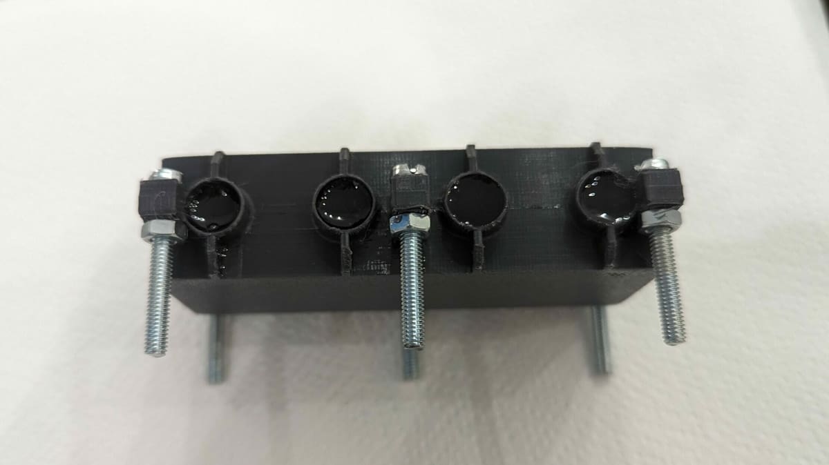
- Spray it with mold release where it will be in contact with the urethane. If you don’t have any, use oil or vaseline, but keep in mind that they will leave a texture on the surface of the part. So, you’re better off with mold release.
- Next, bolt the two halves together and ensure all the seams line up.
Tip
Since we’re using an FDM printer, it can be useful to add a fine layer of vaseline to the inner faces where the two mold halves meet, making sure not to block the air vents. This will help the mold seal. It’s not strictly necessary, but as we said above, it could be useful.
Step 2
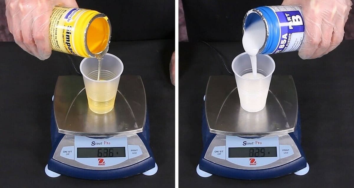
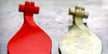
For our molded part, we’re using Simpact from Smooth-On, which is a two-part urethane rubber. In this step, we’ll be mixing parts A and B together thoroughly in the proportions described in the instructions.
This mix is 8.5 parts of A and 10 parts of B. You have to do this by weight because the two parts have different densities. For our mold, we’ll need 37 g total of material.
- Mix each material in its own container before adding them together. This step is critical! Shaking the container won’t suffice. While mixing, make sure to scrape the bottom of the containers.
- If you want to add color to the component, add one drop to part A, then mix it before adding part B to the mixture.
- Pour out 17 g of part A.
- Now add 20 g of part B.
- Mix the combination thoroughly.
Step 3
Finally, we’re going to cast the part.
- Once the material is well mixed, gently pour the urethane through the spout we created in our model. You have about 4 minutes to pour the material before it starts to set, so work fast. Fill it to the point where there is some material in the spout section.
- Now, just wait 2 hours for it to set up.
- Unbolt the mold and use a knife or flat headed screw driver to start separating the two halves. This can be quite difficult, so you may need another pair of hands to help out.
- Gently pry the part out, being careful not to damage it. It’s best to use tweezers and start at the top section where the spout was because this part is not actually a part of the final component.
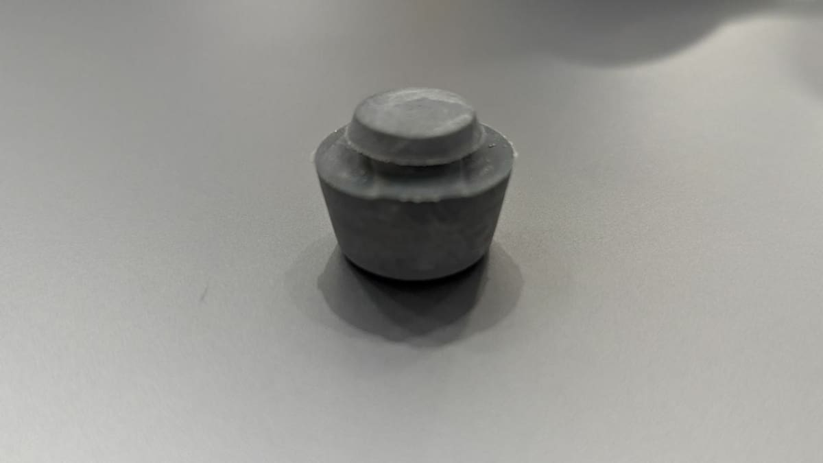
- Once the part is out of the mold, use a sharp knife to remove the additional rubber material at the top where the spout was.
You should now have a new set of legs for your now quieter and slightly taller Prusa MK3!
License: The text of "3D Printed Molds Tutorial: How to DIY Your Own" by All3DP is licensed under a Creative Commons Attribution 4.0 International License.