Top Simulation Software for 3D Printed Parts

Iterate virtually and 3D print your part right the first time with software simulation tools that help you resolve part problems before you print.
Understanding how your part design will behave under stress is critical to industrial designers, engineers, or anyone in 3D printing. In fact, engineering simulation software has evolved. It’s become easier to use and moved beyond highly specialized applications into mainstream product design and development, enabling more people to save time, reduce costs, and innovate.
When designing a functional part, destructive testing of prototype after prototype wastes enormous amounts of time, material, and money. Sure, some field testing is necessary, but software simulation today can dramatically reduce the time you spend reengineering parts and components. This is ideal when working under tight deadlines or even as a side project.
Learning that you need to redesign sooner and understanding the mechanics (or mechanical problems) behind your design, makes you a better designer. The ability to understand the mechanical performance of your design before producing it is powerful, especially in additive manufacturing, where you’re often building unique parts that haven’t been built before using materials that may never have been used before.
Let’s take a look at the best simulation tools and practices that help you go from idea to final part smarter.
Simulation Software
Virtual stress testing gives you an estimate of your current design’s suitability for its task and where you can improve. Understanding the mechanics of your design will allow you to see which design features can alter the stress behavior of specific regions in your part. This comes into play when you’re designing for manufacturing, which is when you’re conscious of how the design will be produced (injection-molded, 3D printed, CNC machined, etc.) or if it can be produced at all.
For example, perhaps the infill you’ve selected to lightweight a bracket actually makes it too weak for its task, or perhaps the heat sink assembly you’ve redesigned to consolidate parts into one complex shape doesn’t function as expected. These are problems that can be uncovered and corrected with simulation software.
New software tools directly address 3D printing in simulation, while others have expanded to incorporate additive manufacturing design principles.
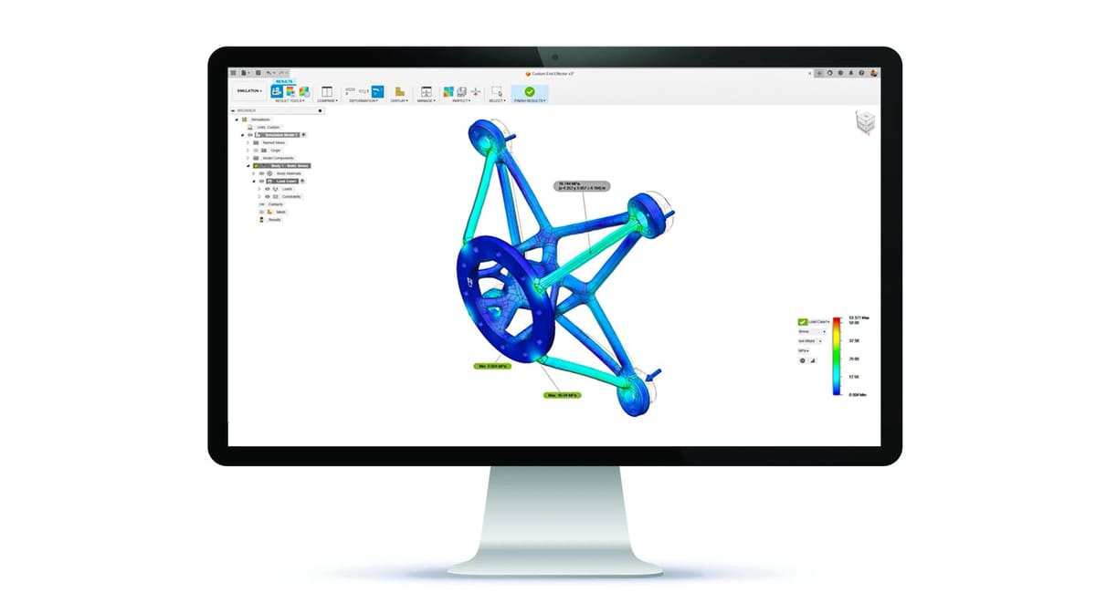
But which simulated tests provide the necessary information? Below, we’ll look at the simulation tool within one of the most popular and affordable computer-aided engineering software tools, Fusion 360 (today called just Fusion), as an example of how these programs work in general.
We’ll show you how to apply simulated tests using Fusion. Then, we’ll look at a few of the differences in simulation analysis from other industrial software, such as Ansys, Creo Simulate, NX, and Abaqus, and the more robust simulation environments they offer. We’ll also touch on process simulation software, which are products that simulate the process of 3D printing itself to enable you to predict and correct build failures, such as warping and distortions before they happen in the build chamber.
But wait, first you need to understand some mechanical engineering concepts, if you don’t know them already – most importantly: finite element analysis (FEA).
What is Finite Element Analysis?
FEA is the study of how a part or assembly interacts in its environment, whether that’s heat and pressure in an engine or cold and weightless in space. It considers the mechanical and material constraints of the part and applies that to a digital simulation. The overall goal is to understand how the part will behave under specific stresses and strains.
In more technical terms, FEA is the simulation of any given physical phenomenon using a numerical mathematic technique called finite element method (FEM). Don’t worry, the software mostly does the math for you.
As we already mentioned, simulation saves time building prototypes and conducting experiments, saves money in material to build prototypes and test rigs to test the prototypes, and external help, such as machinists to make more iterations.
In the additive manufacturing industry, using FEA is key to saving development time and cost. But there’s more. Other benefits of incorporating FEA into your AM workflow include:
- Better understanding of the material selection and options
- Better understanding of the appropriate testing scenario to stress your part accurately
Although FEA has enormous benefits, it does not remove the necessity for some physical testing. Testing is still required. There is a difference between simulating (FEA) on a computer and testing on your test rig in a real-life scenario. But simulation generally keeps you from conducting the wrong physical tests, going down the completely wrong design path, and building with inappropriate materials.
As you continue to work with FEA and the FEA software tools, you’ll better understand how many force-specific applications are required and how this can determine the success or failure of your analysis. For newcomers to the process, feel free to simulate many times until the results make sense.
From there, you’ll be able to modify your design accordingly, prototype it, and then test it in a real-life scenario. Compare your analysis to the accurate life test results to improve either your physical testing or your simulation setup and parameters, or both.
FEA software, or computer-aided engineering (CAE)/computer-aided design (CAD) software with FEA tools, is generally sophisticated and should be run on hardware capable of running simulations without bogging down. Later in this article, I go over the software packages available for running finite element analysis on your 3D printed parts and their system requirements, which are important to note.
Setting Perimeters for Simulations
There are a few more things you should know about FEA to get started. Mainly, that, although the software simulates the stress, you still need to tell it how to simulate the stress and what it is simulating stress on.
There are a few different kinds of simulation within FEA/CAE software packages.
- Static analysis studies the deformation of a part concerning the stresses and strains placed. This is one of the most common types of structural analysis.
- Dynamic analysis introduces noise, vibration, and acceleration into the mix.
- Multibody dynamics, on the other hand, includes stresses on a multi-dimensional, complex assembly with multiple moving parts, such as an engine. The main goal is to understand not one but several forces operating within a system and how these external factors influence each part.
Getting into the setup of your analysis, there are a few things to keep in mind. Depending on your application, there may be an industry standard to base your study on. This makes it easier for you to set up. Typically, these standards include boundary conditions and initial parameters depending on your application. Sometimes, there are the initial parameters used to define the study, such as force applied, material properties, angle of attack, pressure, direction, etc.
Another important term, the factor of safety, refers to the ratio between how strong the part is relative to the maximum stress at that part. Ensure that you set up your study properly with appropriate boundary conditions and assumptions made.
Running your simulation should involve the following steps:
- Model the part or assembly using CAD software
- Generate the mesh model
- Determine an industry-standard or relevant boundary conditions, if applicable
- Run the simulation
- Post-process and analyze. Make conclusions and, if needed, refine your mesh or redesign your part and rerun the simulation.
Keep in mind that running an FEA simulation is not a one-and-done process. It is an iterative process involving testing initial parameters and initial design. Then you take the results, analyze them, improve the design, and retest. Rinse and repeat until the results are within the success criteria that you’ve outlined at the beginning of the study. If no design change is required, you have a working design that you are confident will provide acceptable performance.
Simulation in Fusion
Now that you’re familiar with FEA, let’s discuss what Autodesk offers within Fusion and as an optional simulation extension.
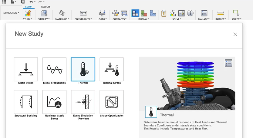
Within the base subscription of Fusion there are simulation tools, including:
- Static Stress
- Model Frequencies
- Thermal Analysis
- Thermal Stress
- Structural Buckling
- Nonlinear Static Stress
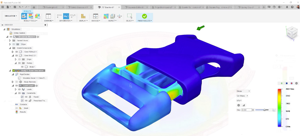
- Event Simulation
- Shape Optimization
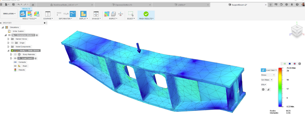
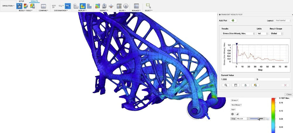
Static stress will allow you to determine the maximum stresses and displacements of your model or assemblies. Modal frequency comes into play when dealing with vibration in your system. Thermal analyses take care of thermal distribution and how that affects your parts. Buckling aims to understand what happens to a part under compression or how it fails. Understanding non-linear stress allows you to analyze permanent deformation using non-linear materials in your assemblies. Event simulation introduces time dependence into your model, which is extremely useful for real-time simulations.
Most of my experience with FEA comes from both non-linear stress analysis and event simulation. The point to cover is shape optimization which introduces how to make components lightweight or stiff, providing cost efficiency and sustainability in production.
I’ve used Fusion’s FEA software to improve the design of a camera mount for one of my clients. Running a product development company, I’m tasked with enhancing the clients’ design and ensuring the design can satisfy their requirements. Using FEA, I was able to determine:
- What was the optimal design for the mount used within its environment
- What forces the part would experience over time
- Additional reductions and modifications to maintain the rigidity of the mount
Since the mount was subjected to high gravitational forces (drifting, abrupt changes in acceleration), I conducted an event simulation to understand the longevity of the part and how to refine the design further. I decided to go with Fusion 360’s FEA software, given that Autodesk has been improving its software package with frequent updates. Fusion is also relatively affordable for smaller startups.
Not to mention, Fusion includes very handy additive manufacturing and generative design toolkits and I like to keep my workflow contained to one software package where I can design, improve, analyze, and manufacture.
Of course, if you want to get far more sophisticated with your simulations in the Autodesk ecosystem, there’s a Fusion Simulation Extension ($1,465 / year). This extension has more robust simulation tools, including:
- Nonlinear Static Stress: large deformation, motion, contact, and load change behaviors)
- Structural Buckling
- Event Simulation: predict how time-dependent forces influence 3D design performance.
- Modal Frequencies: Inspect the effects of natural, free vibration on your part
- Injection Molding
- Electronics Cooling: identify risk of electronic component and part failure due to overheating
- Generative Design: explore multiple outcomes that meet your design specifications while reducing weight and improving performance.
- Thermal Simulation: Trace heat transfer and temperature-induced stresses
The Injection Molding Simulation is especially useful to compare how your 3D printed parts will perform compared to the same part injection molded.
Autodesk also offers an additive manufacturing simulation tool as part of the Additive Build Extension for Fusion, but it’s not an FEA tool, rather it allows you to replicate real-world additive manufacturing processes (selective laser sintering, powder bed fusion, etc.) and predict distortion and common print failures. Based on simulation results, Fusion can automatically compensate geometries to achieve the desired shape when 3D printing. A more advanced version of this function is available through Autodesk’s Netfabb software.
But, Fusion core FEA is a good introduction tool for those less familiar with the technology. It uses a “stripped” version of Autodesk Nastran, keeping the software user-friendly. Check out this handy tutorial covering how to set up simulations in Fusion.
There are far more powerful simulation programs, of course. Some of the products we touch on below are capable of not only simulating virtually any stress or event, but they can also help you redesign your part better. These solution also incorporate multiple levels of simulation at every stage of the product life cycle – from concept through printing to quality assurance – to create a full closed loop.
Top Software for Simulation
As you continue to learn, you may find other programs better suit your needs depending on your application and your industry. The biggest takeaway is to understand what you’re looking to get out of FEA, determine if a particular tool achieves that better than the other and run your simulation. Don’t be afraid to try multiple tools (most have a free trial period). The ones listed below are not ranked one better than the other because the need for simulation tools varies dramatically from one company to the next.
The software packages below allow for more in-depth non-linear simulations, multiphysics, fine-tuning a mesh, and the ability to use different elements. Some not only run through various simulated scenarios but also suggest the optimal design direction.
Another sophisticated feature you may find in some simulation applications, and well beyond what we’ll cover here, are digital twins, which are complete virtual prototypes of real-world systems.
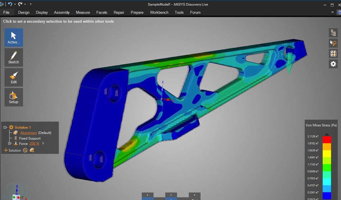
Ansys Discovery Simulation 2024 R1
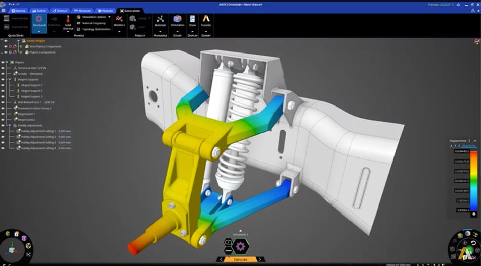
Perhaps one of the most in-depth CAE software packages is from software publisher Ansys. Rather than starting with a design then refining through simulation, like Fusion, Ansys Discovery is a simulation-driven 3D design tool. Providing technical depth per analysis is this program’s strong suit. Not to mention the level of refinement and customization per simulation. It’s used for simulating mechanical design, optics, fluids, surgical implants, and much more.
Ansys offers several software packages, including Ansys Mechanical (easy to use, general multipurpose tool), Ansys Fluent (for advanced physics modeling), and Ansys LS-Dyna (for non-linear simulations, multiphysics, etc.). They also offer free trials, limited to a certain number of nodes it can solve, but worthy of a trial run.
Ansys also includes an Additive Suite (additive, as in additive manufacturing or 3D printing) that features:
- Additive Preparation
- Additive Print
- Additive Science
Last year, Ansys added a virtual assistant in the form of AnsysGPT in order to help make simulation tools easier and faster. According to chief technology officer, Prith Banerjee, AnsysGPT is “a natural language interface to the kind of questions that normally our field application engineers would respond to.” According to Banerjee, “AI is really good at looking at all published training material and providing a very quick and accurate resolution to an issue. In the very near future, we will have natural language interfaces to all our products.”
Ansys 2024 R1 continues to expand toolsets for additive manufacturing users, streamlining workflows between design, simulation, and manufacturing. Ansys Mechanical can now identify and minimize risk for build errors and ensure quality parts through process simulation for metal powder bed fusion (PBF), directed energy deposition (DED), and metal binder jetting, the company says.
These tools can help provide better print design, design for additive manufacturing (DfAM), process simulation, and build support. Note that Ansys also has a more stripped-down 3D modeling version of Discovery that doesn’t include all of the same robust simulation tools.
- Systems Requirements: Windows 10/11 64-bit, graphics resolution 1024 x 768 or higher, 4 GB of dedicated graphics card memory.
- Price: ~$3,000 / year
Dassault Systèmes Simulia 2024
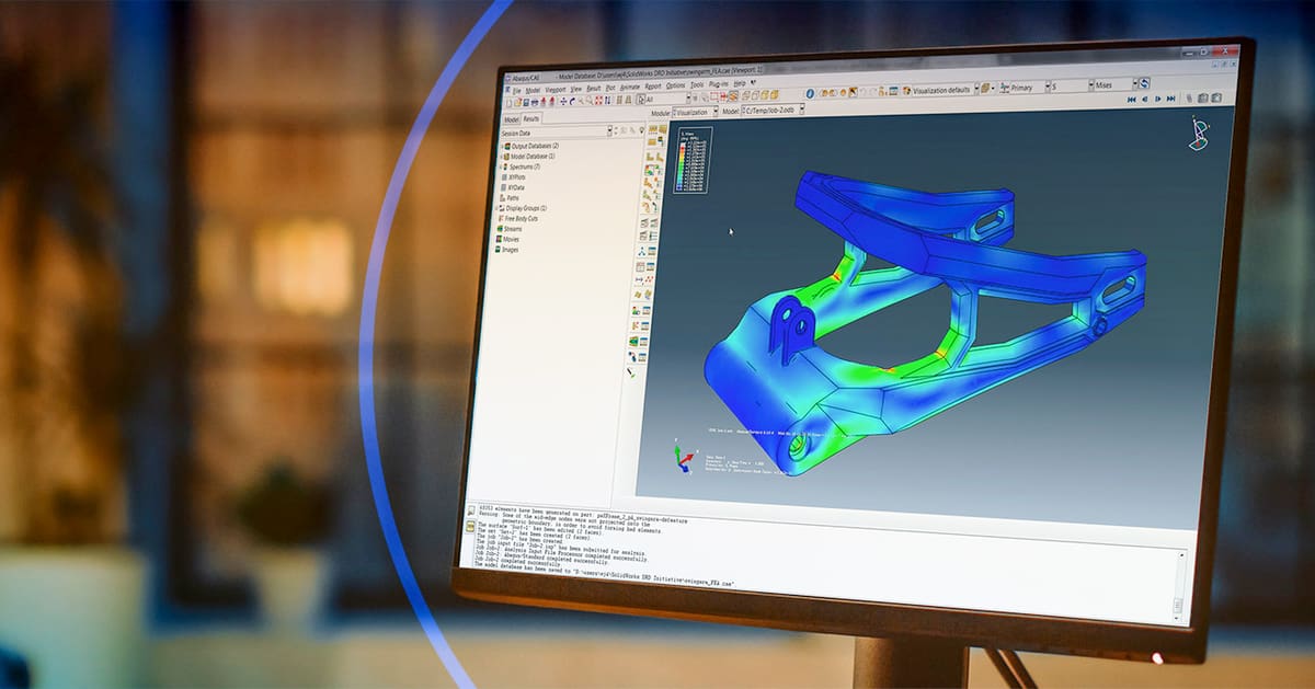
Simulia by Dassault Systèmes (maker of Solidworks) if a robust tool that accelerates the process of evaluating the performance, reliability, and safety of materials and products before committing to physical prototypes.
It provides a wide range of simulation types, such as multiphysics, computational fluid dynamics, standard mechanical static analyses, just to name a few. This is an attractive solution for engineers in, for example, the automotive industry who need to simulate a lot of different effects from vehicle loads and vibration to crash and acoustic-structural coupling.
The Abaqus Unified FEA is an optional product suite for Simulia. It has three modules (Standard, Explicit, and Multiphysics) that can manage both routine and sophisticated engineering problems covering a vast spectrum of industrial applications.
Within Simulia there are optional tools within modules within extensions in an almost indecipherable layering of features, which is why it’s sold through resellers trained to uncover what exactly you’ll need it for and which options you should buy.
Like Ansys, Dassault Systèmes offers an additive manufacturing-specific tool called the Print to Perform simulation for Additive Manufacturing. This solution features a Part Selection tool to identify candidates for additive manufacturing, a Function Driven Generative Design application that unifies modeling, simulation, and part optimization in a single environment, and printing process simulation.
We’ve really just scratched the surface here, and there really isn’t a simulation I can think of that Simulia can’t do.
- Systems Requirements: Windows 7/8/10 64-bit
- Price: Simulia is a modular tool and pricing is customized to your needs. There’s also a free Student Edition.
Comsol Multiphysics 6.2
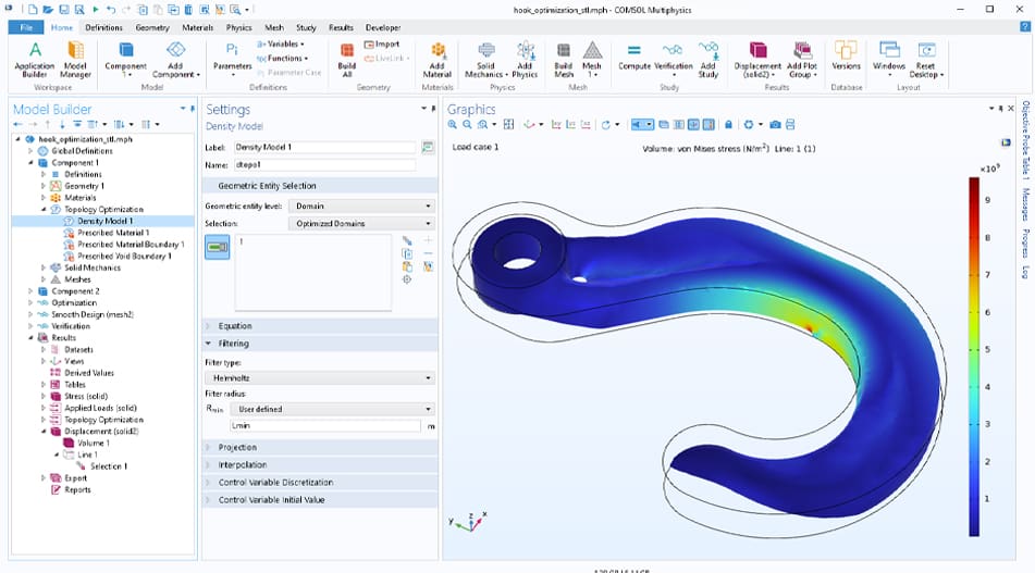
Not for beginners, the Comsol Multiphysics software is used by engineers and researchers to simulate real-world designs, devices, and processes across industries. Common uses cover battery design and fuel cells, semiconductor devices, microfluidics, and product design of parts that feature chemical reactions.
It’s another multi-module solution that aims to cover all the bases of engineering simulation from fluid and heat to chemicals and sound, enabling you to select just the modules you need. Updates in version 6.2 have resulted in faster computation speeds and improved user experience, the The latest version now uses a new surrogate model framework which allows for more accurate digital twins.
Fortunately for those with less experience, it integrates with a long list of CAD programs including Revit, AutoCAD, Solidworks, Solid Edge, and others. The Comsol Multiphysics with “LiveLink for Solid Edge”, for example, is an integration that helps you optimize designs through simulation while providing concurrent updates to your designs during the simulation process. Bidirectional updates are automatic when both programs are open at the same time and you are solving an optimization study or running a parametric sweep. The integration doesn’t feel like your switching between two different programs.
In a past life, I used Comsol for running fluid flow simulations.
- Systems Requirements: Windows 10+, macOS 12+, Linux; graphics memory of 2 GB
- Price: There’s a base price of around $1,800 / month, then specific simulation models are extra.
Siemens Solid Edge & NX 2024
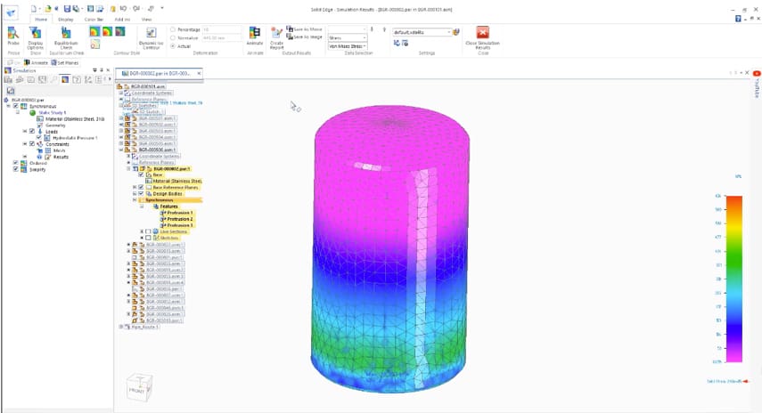
The entry point to the robust world of Siemens software for most product designers is the company’s CAD tool Solid Works, which has built-in finite element analysis (FEA).
Based on finite element modeling and Simcenter Nastran FEA technology, Solid Edge Simulation features a full motion simulation suite so you can evaluate and visualize how parts will interact in an assembly, understand how a product will perform throughout its operational cycle, and how it will function in the real world.
Siemens developed Nastran for NASA in the ’60s. It offers multidisciplinary structural analysis, non-linear analysis, embedded fatigue, and vibration fatigue analysis. A new, automated mesh generation processes in Solid Edge Simulation provides a mesh with minimum effort, controlling mesh without the need for parameters.
In their latest update, Solid Edge 2024 has focused its improvements on elevating its user experience, the company says. Using AI and the cloud, visualizations are now faster and add-on products are available on demand.
The FEA inside Solid Edge is a capable tool, but advanced industrial designers would opt for the state-of-the-art full featured simulation environment in Siemens NX and Simcenter 3D.
If your company uses Siemens NX software, probably the most robust of the engineering and manufacturing product suites out there, then you may know about its advanced simulation capabilities.
Siemens, like Ansys, boasts a “complete simulation workflow” for additive manufacturing, which means there’s simulation at the design stage with design validation tools, the engineering stage, the manufacturing stage, and even at the post-processing and quality inspection stage. This closed-loop solution lets you compare scan data from the final 3D printed part to the original design.
Software like this, and some of the others mentioned, is what’s driving the use of additive manufacturing in large industries from automotive to aerospace where teams collaborate and the entire data-rich process is integrated.
- Systems Requirements: Windows Pro 10+, 16+ GB RAM
- Price: $263 / month Classic, $378 / month Premium
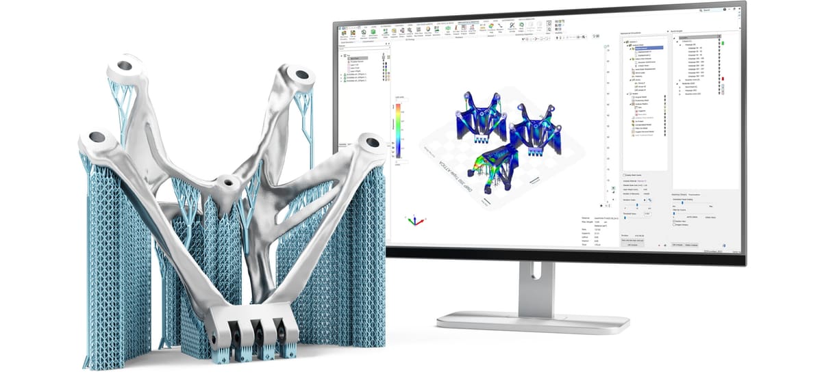
Altair Inspire Print3D
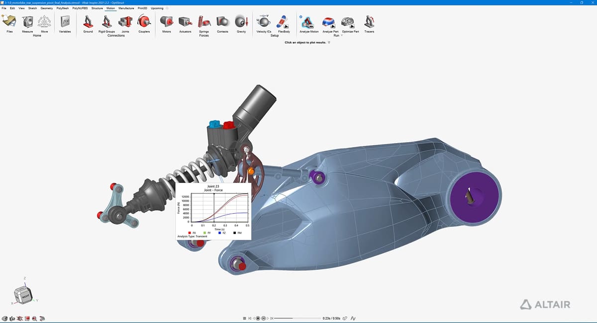
When it come to simulation solutions from Altair, it’s hard to know where to start. If it can be simulated, Altair has a tool for it. There’s practically no industry for engineers, designers, and researchers not covered by Altair.
So here, let’s focus just on the 3D printing and DfAM features.
Groped under their “Industrial Design” category, Altair offers tools for design, visualization, and topology optimization, while under their “Manufacturability” category you’ll find all of their simulation tools. There are modules to evaluate product feasibility, optimize the manufacturing process, and run virtual try-outs for many traditional, subtractive, and additive manufacturing processes enabling comparisons.
Altair’s applications for product manufacturability are tailored to several industries, including automotive, aerospace, electronics, pharmaceutical, and heavy industry. In fact, there are about two dozen simulation programs, including Inspire Print3D, which is specific to creating structurally efficient 3D printed parts using selective laser melting (SLM).
Altair products integrate with the process simulation software Amphyon by Additive Works, covered below.
Altair, like some of the other software packages here, is expensive but they have a special offer for start-ups. The Altair Smart Product Development package is a three-year software plan tailored for startups in product development. Whether you’re developing smart connected products, components for e-motors, renewable energy solutions, industrial machinery, or verifying a design for manufacturability, you can get a special rate on Altair products.
- Systems Requirements: Windows 10+, 8+ GB RAM (32 GB is recommended)
- Price: Pricing is customized to your needs. There’s a free trial.
nTop 4
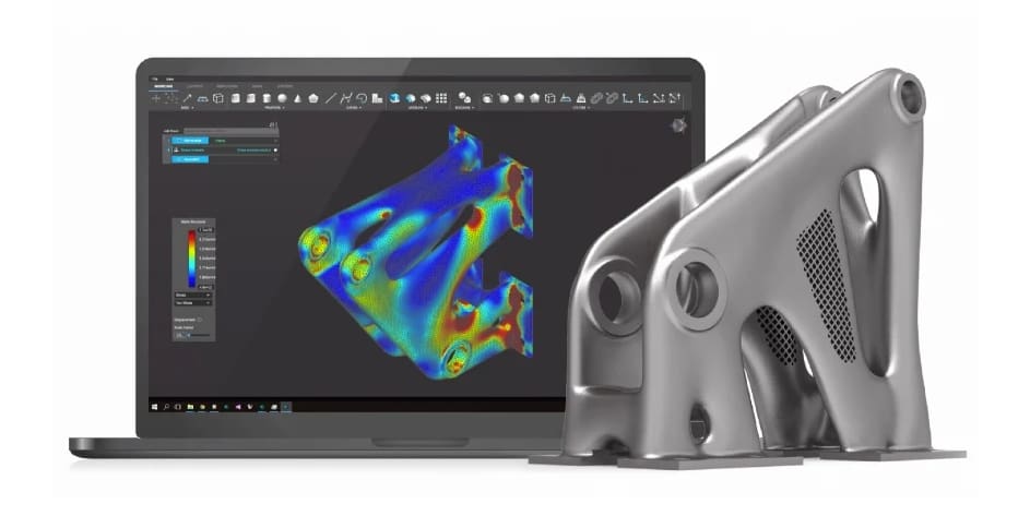
nTop (formerly nTopology) is perhaps best known as a topology optimization tool, but it’s much more than that. It features built-in FEA tools that couple design generation with design analysis to reduce the time it takes in development. Unlike some other tools, but pushes engineering simulation from the middle and late stage of the design process to the very front.
nTop’s integrated mechanical and thermal FEA enables you to build multiphysics control systems into your design workflows and verify the performance of generated parts without passing them to your team’s analysts.
Pre-process FEA models in nTopology before you export high-quality meshes to your preferred CAE suite or more robust FEA software for detailed verification. For a more detailed evaluation of nTop 4, check out our article here.
- Systems Requirements: Windows 10, 64-bit; 64 GB RAM; graphics card NVIDIA GeForce 1080, NVIDIA Quadro P4000 or better.
- Price: $15,000 / year, free for students, educators, and researchers with membership in the nTop Ed community program
SimScale
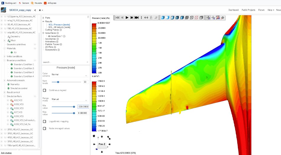
Cloud-based solution, SimScale, offers an all-in-one simulation package with access to FEA. Using cloud-based software may render ease of use since you only require an internet connection. SimScale setups you up with a high-performance computing machine for your analysis, allowing you to run simulations from anywhere. Similarly, ANSYS Mechanical also has an option to run from the cloud. I support cloud simulation since it makes simulations more accessible and easier to analyze your applications.
SimScale is a computer-aided engineering software product based on cloud computing. SimScale was developed by SimScale and allows computational fluid dynamics, finite element analysis and thermal simulations.
The FEA component of SimScale enables you to virtually test and predict the behavior of structures and solve complex structural engineering problems subjected to static and dynamic loading conditions.
- Systems Requirements: Cloud-based
- Price: ~$4,800 / year. Free version for qualified users, and free trial.
PTC Creo Simulate
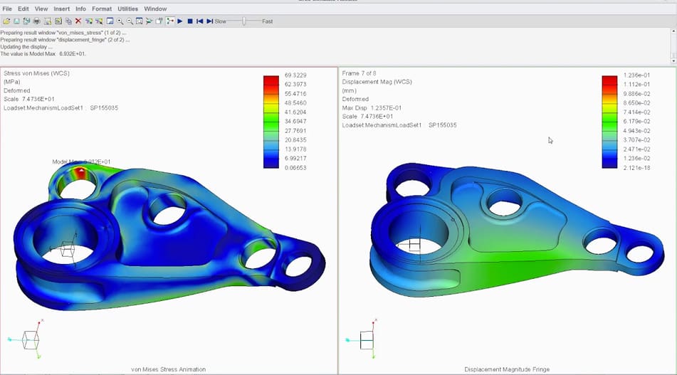
One of the familiar programs in the medical device industry that I’ve used is PTC Creo Simulate. I’ve used this program to run several analyses on orthopedic implants, such as determining the stress distribution between the acetabular cup and femoral head when a load is placed. In this case, I had to refer to applicable industry standards that provided the force load values, angles, orientation, etc. This allowed me to save time as all the parameters and boundary conditions were identified.
You may be familiar with Creo as a CAD tool. The simulation extensions, which are all a collaboration with Ansys, are optional and the basic one covers:
- Structural Analysis
- Thermal Analysis
- Modal Analysis
- Computational Fluid Dynamics
There’s also an advanced simulation extension that covers nonlinear static structural analysis, dynamic structural analysis, and a menu of more advanced features. The Fatigue Extension covers the evaluation of product design for durability and more extensions cover everything from ergonomic fit to injection molding of plastic parts.
- Systems Requirements: Windows 10 Pro+, 8GB RAM, dedicated NVIDIA GPU card
- Price: Pricing is customized to your needs. There’s a free trial and a special Creators Program offer for startups.
Software To Simulate the AM Process

When it comes to additive manufacturing, there’s another type of simulation software not to be confused with FEA.
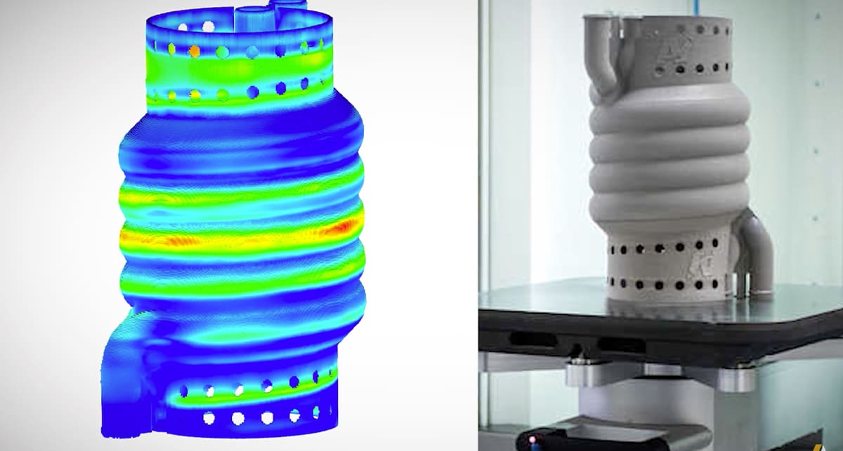
Process simulation software tools simulate the additive manufacturing process itself, in other words, they take your digital part design and simulate building it through a 3D printing process, such as laser powder bed fusion or metal binder jetting.
The goal of this type of simulation is to test the buildability of your part in the first place, predict build failures, support failure, and estimate warpage and other possible defects that could occur during the build process that you may be able to compensate for. The software shows you how things such as the number of parts in the build space or the support structures influence your final part.
These solutions are also sought after as a way to certify that your part was 3D printed to spec. Many of these programs can issue layer-by-layer reports certifying that there were no build anomalies.
You can combine and integrate these simulations with your FEA simulations for a fuller picture of your additively manufactured part. Some simulation software mentioned above, such as Ansys 2024 R1, Netfabb, and Abaqus, have this capability already built-in. Some 3D printer makers also offer software, such as Live Sinter software from Desktop Metal, tuned to their machines and the known performance over thousands of builds.
But if your software or printer manufacturer doesn’t offer a process simulation tool, or you’re looking for a stand-alone option, check out the software below.
Simufact Additive 4
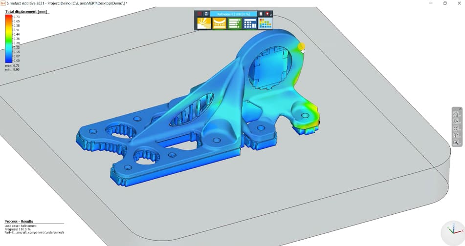
Simufact, by Hexagon Manufacturing Intelligence, is a software specializing in simulations for metal parts in three groups, forming, joining, and additive manufacturing. Their AM product, called Simufact Additive, includes simulations for powder bed fusion, metal binder jetting, and deposition methods.
This scalable process simulation environment boasts ‘first-time-right’ optimization of metal additive manufacturing predicting the final distortion and residual stresses of metal 3D printed parts.
Simufact Additive is a standalone product that already covers important parts of the digital process chain in additive manufacturing. In combination with software solutions, you can create a complete end-to-end product simulation.
Simufact also is the technology inside Materialise Magics Simulation Module.
Oqton Build Quality
Oqton, an independent software subsidiary of 3D Systems, offers an “AI-enabled” Build Quality suite used to monitor, track, and inspect quality metrics of metal powder bed fusion builds throughout the additive manufacturing process
The solution has three modules that can work independently or together: Build Simulation, to prevent predictable anomalies and defects; Build Monitoring, to detect on-line anomalies; and Build Inspection, to inspect and correct anomalies and defects.
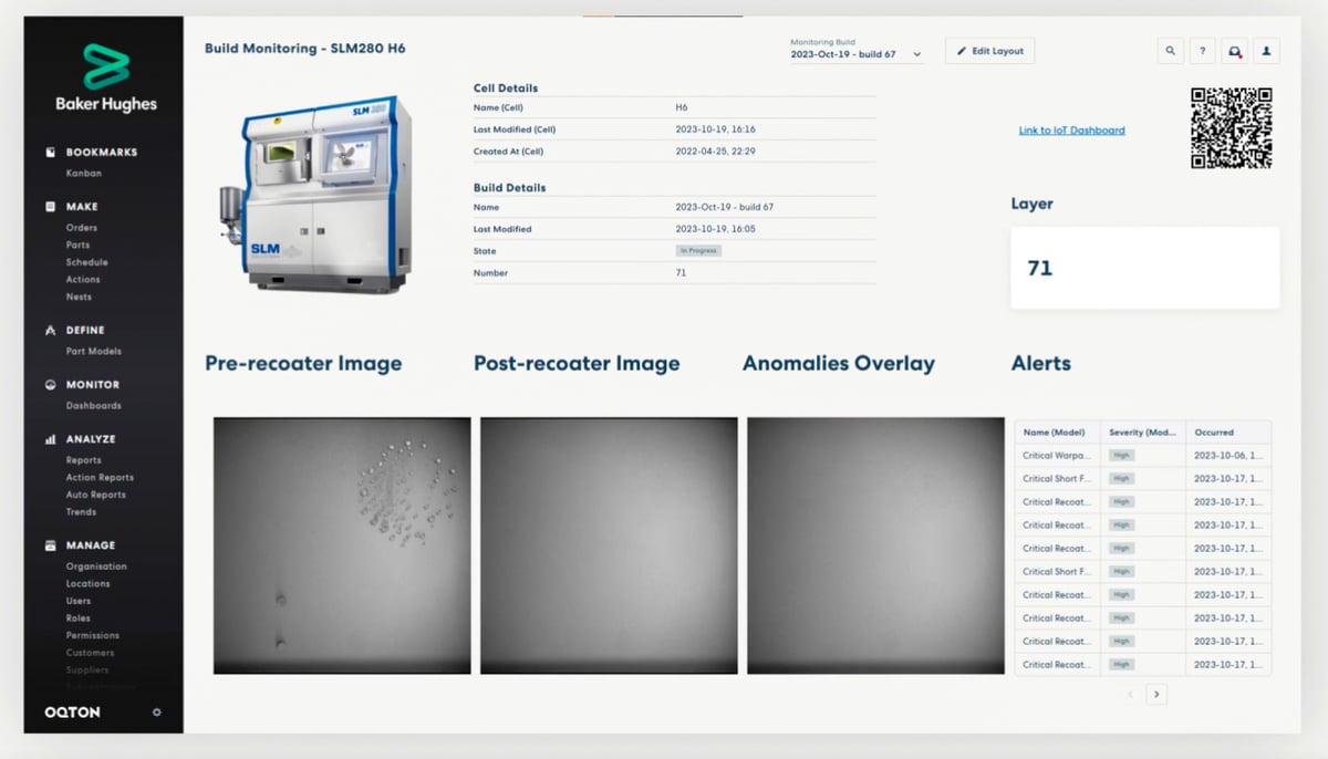
The goal is to enable you to monitor builds in real-time so you can make fast decisions to reduce scrap related costs. The build inspection gives you the tools to determine the success of a build and generate detailed quality reports. And in the case of a failure, it can infer root causes and correct build procedures to correlate with simulation and scan path analyses.
Note that Oqton is not tied to just 3D Systems hardware. You can run it with your SLM/Nikon, EOS, HP, Trumpf, and others.
Flow-3D AM
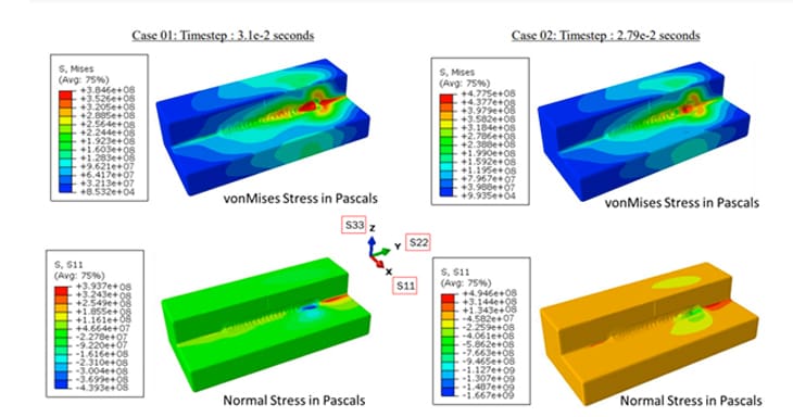
Flow-3D AM offers process modeling tools based for 3D printing on metal laser powder bed fusion machines. The tool takes into account process parameters such as laser power and speed, scan path, hatch spacing, powder size distribution, and powder bed packing to determine how they will influence the AM build of your part.
Through modeling, you can understand the effects of these process parameters on underlying physical phenomena such as melt pool dynamics, porosity formation, solidification, and microstructure evolution. These insights can then drive the development of process windows for alloys that take full advantage of the benefits of additive manufacturing, the company says.
AdditiveLab
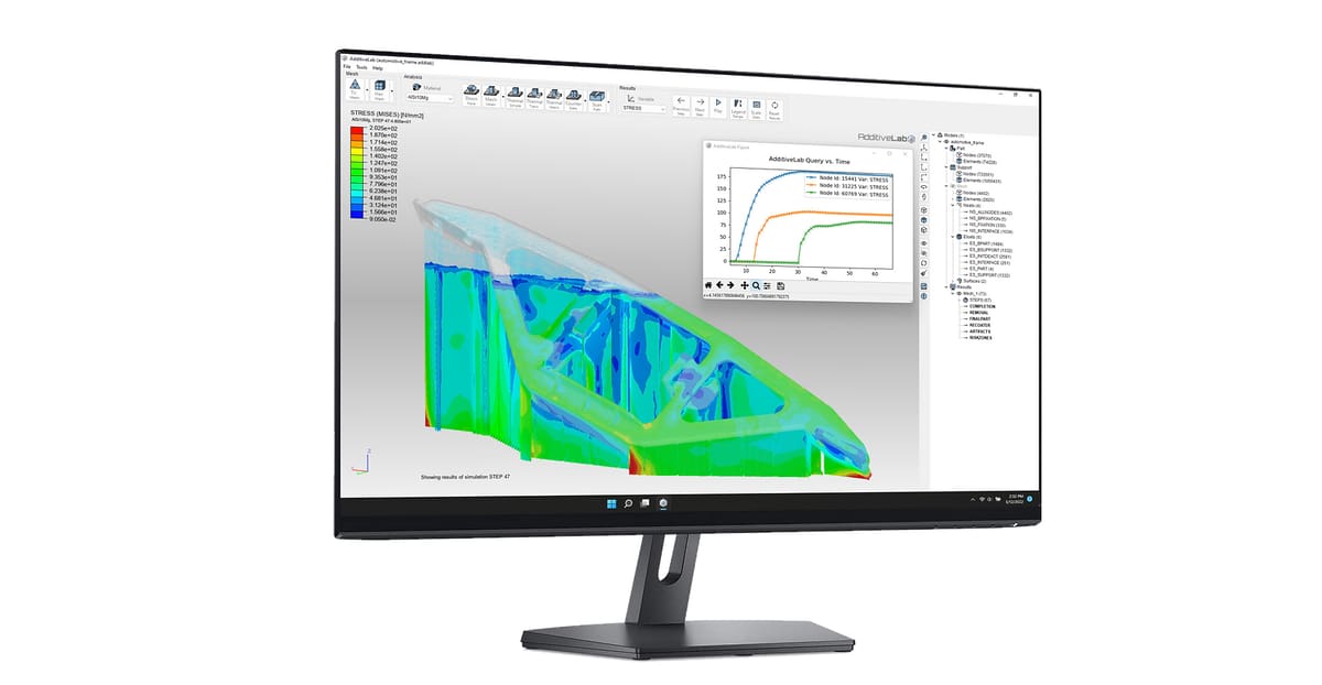
AdditiveLab software is at its core a tool for the simulation of metal parts before they’re printed. This Belgian start-up developed a process simulation tool to predict and correct defects in 3D printed parts and reduce distortions.
AdditiveLab software can predict regions that suffer from localized and global overheating and may lead to undesired mechanical properties or defects such as melt ball formation. With more insight into potential manufacturing outcomes, entire build configurations including part and support structures can be optimized to increase the process efficiency and to minimize manufacturing risks.
By using the AdditiveLab Python API, advanced simulation users, researchers and AM teams have the power at their disposal to create customized simulations, optimize their processes, and create their own simulation IP.
1000Kelvin
Just launched in Nov. 2023, 1000Kelvin, is a software startup specializing in AI-powered solutions specific to additive manufacturing. Its platform, called Amaize, autocorrects print recipes to ensure the successful production of AM parts.
Amaize is not something you can buy and install on your metal laser powder bed fusion machine, rather its a solution integrated by OEMs. So far, you can find it on EOS machines.
Amaize works by analyzing the scan strategy your metal LPBF machines plans to use on a particular build to predict process anomalies leading to potential defects based on machine learning from historical build data. It can tag problematic vectors and regions for correction or optimization. It can automatically correct the scan strategy and problematic regions or you can do it yourself. You then upload the new correction strategy directly to the machine.
Lead image source: Autodesk Fusion 360.
License: The text of "Top Simulation Software for 3D Printed Parts" by All3DP Pro is licensed under a Creative Commons Attribution 4.0 International License.
CERTAIN CONTENT THAT APPEARS ON THIS SITE COMES FROM AMAZON. THIS CONTENT IS PROVIDED ‘AS IS’ AND IS SUBJECT TO CHANGE OR REMOVAL AT ANY TIME.