Gyroid Lattices in 3D Printing – The Ultimate Guide

Prized for their unique mechanical, geometric, and physical properties, designing with gyroid lattice structures makes your 3D printed parts lighter, smaller, and cheaper to manufacture. Learn how!
Nature has long been the inspiration for books, poems, music, and art, but it’s also inspiring to engineers. Biomimicry, or using nature to inspire design, has led to countless products from Velcro (prickly burrs) and wind turbine blades (humpback whale fins) to energy-efficient building designs (termite mounds) and drone propellers (owl wings).
One nature structure increasingly applied in 3D printing to make products lighter weight, and make lighter weight products stronger is the gyroid lattice. Once, nearly impossible to manufacture, this complex shape is no challenge for 3D printers, opening up a new world of product design.
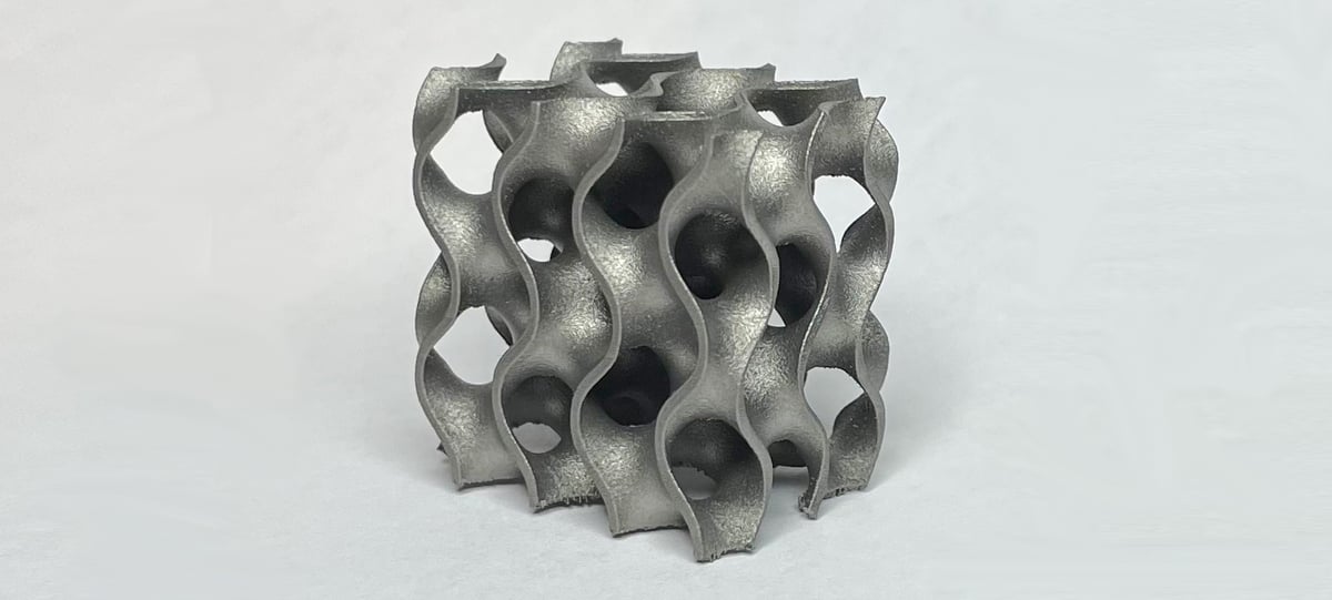
Gyroid structures are complex three-dimensional geometric patterns characterized by their intricate network of repeating surfaces that minimize surface area while spanning a given boundary. Technically they are a triply periodic minimal surface (TPMS) structure, which we dive deeper into below.
Gyroids in Nature

In a twist to the idea of nature inspiring engineering, physicist Alan Schoen, who just died last month as age 98, first introduced the concept of the gyroid structure mathematically in the 1970s. It was only after he presented the concept that the gyroid lattice has been located in nature, including in certain types of sea sponges and marine animals, and mineral crystals.
The classic example of gyroids in nature is the Blue Morpho butterfly.
These brilliant blue butterflies don’t get their color and iridescence from pigment. In fact, they aren’t pigmented at all. We see the butterfly as blue because the lattice pattern of the cells of the wings causes the light to reflect so that our eye perceives blue. The color changes depending on the angle at which you look at the wings because the lattice reflects light in slightly different ways depending on the angle. What type of lattice can pull this off? A gyroid. (Check out this fascinating video on the Morpho’s structure from theoretical physicist Dr. Sabetta Matsumoto.)
What is a Gyroid?
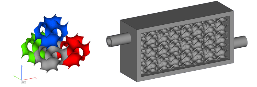
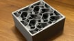
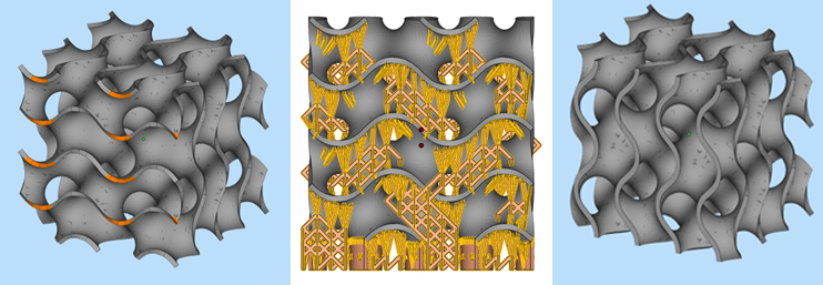
Let’s break gyroids down a bit further. The triply periodic minimal surface means that you can create a pattern of gyroids in three directions. In the image below, the gyroid unit individual cell (in gray) can be copied in the x, y, and z axes, to build a larger lattice, such as the one filling this heat exchanger model.
Minimal surfaces are those that span the boundary points without creating any more surface area than is absolutely required. Although trying to wrap your head around this idea may burst your bubble, don’t worry, because soap films are great at creating minimal surfaces. Think of the film of soap on the ring of a bubble wand.
The soap touches the boundary (the edge of the wand) without creating any extra surface area such as bumps or divots. The soap film will be perfectly flat. It does the same thing for wonky shapes, too. Although this is a two-dimensional analogy, you get the idea of a network of connected surfaces where the film forms a continuous, interconnected surface that spans the frame of the wand.
Why Use Gyroid Lattices in 3D Printed Parts?
Nature is great at optimizing design through natural selection and evolution. Although Alan Schoen “discovered” the gyroid lattice, butterflies had already figured it out.
Schoen was studying these structures for aerospace applications. In addition to producing the iridescent blue color, the gyroid lattice inside the wings of the Blue Morpho has structural benefits too. The gyroid lattice allows the wings to be stiff enough to fly without being heavy and cumbersome.
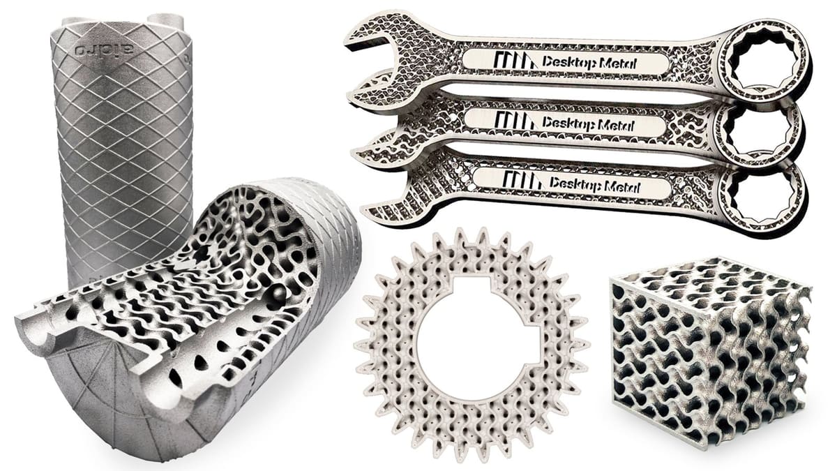
Though the gyroid was discovered decades ago, as we mentioned, there wasn’t a way to manufacture them. Now, with additive manufacturing and gyroid-enabled computer aided design (CAD) software, gyroids are more accessible than ever before.
3D printing and its ability to create gyroid lattices opens up a myriad of possibilities for new variations on existing materials, light-weighting, biomechanics, heat transfer, and more.
Lightweighting
Knowing that the gyroid lattice in a butterfly’s wing helps keep the wing stiff but light weight, researchers from the Mechanical Engineering and Materials Technology Institute at the University of Applied Sciences in Switzerland looked to see how similar structures can be used in engineering.
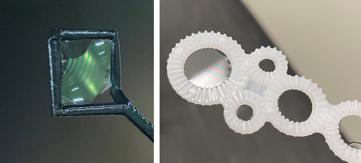
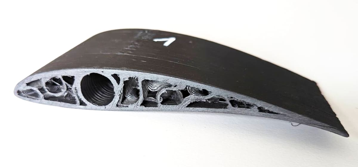
They took the gyroid lattice and combined it with carbon fiber-reinforced plastic ribs, like the ribs seen on a butterfly’s wings. The lattices were built using stereolithography (SLA) with tubes into which they installed the carbon fiber reinforced ribs. From their testing, they were able to produce stiffer lattices without increasing the density. They also investigated how variables like rod thickness and gyroid porosity affected the resulting material. This is only one of many studies looking at gyroid lattices for use in light-weighting applications.
Bone and Tissue Engineering
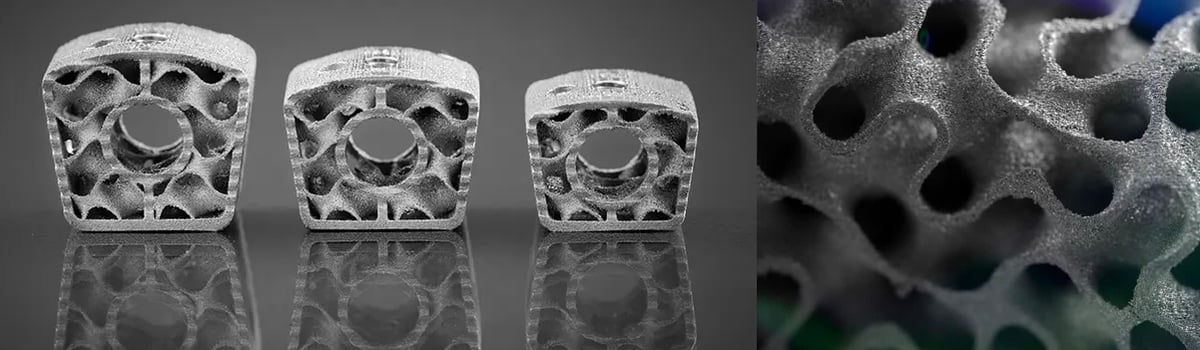
Gyroids present new opportunities for bone and tissue scaffolding. In the event of injury to a bone, doctors install artificial bone implants with scaffolding lattices to replace the damaged area. The mechanical properties of these scaffolds are important, but so is the porosity. Over time, new tissue will grow into the scaffold. Engineers are challenged with designing scaffolds that have enough porosity to allow tissue growth and fluid movement, without sacrificing mechanical properties.
In 3D printed artificial bone implants today, various lattice structures are used to replicate the porous nature of natural bone. Ideally, each lattice, with its own design considerations and benefits, could be selected for the patient’s medical condition, the type of implant, and the desired mechanical and biological performance.
One study found gyroid scaffolds had higher compressive strength than other gyroids studied. Researchers from RMIT University and Deakin University in Victoria, Australia, looked at how well gyroid-shaped scaffolds perform. Their study used PLA via FDM to create gyroids. This study focused on material testing only and whether fused deposition modeling (FDM) gyroids would be a good choice for bone tissue scaffolds and the results are promising.
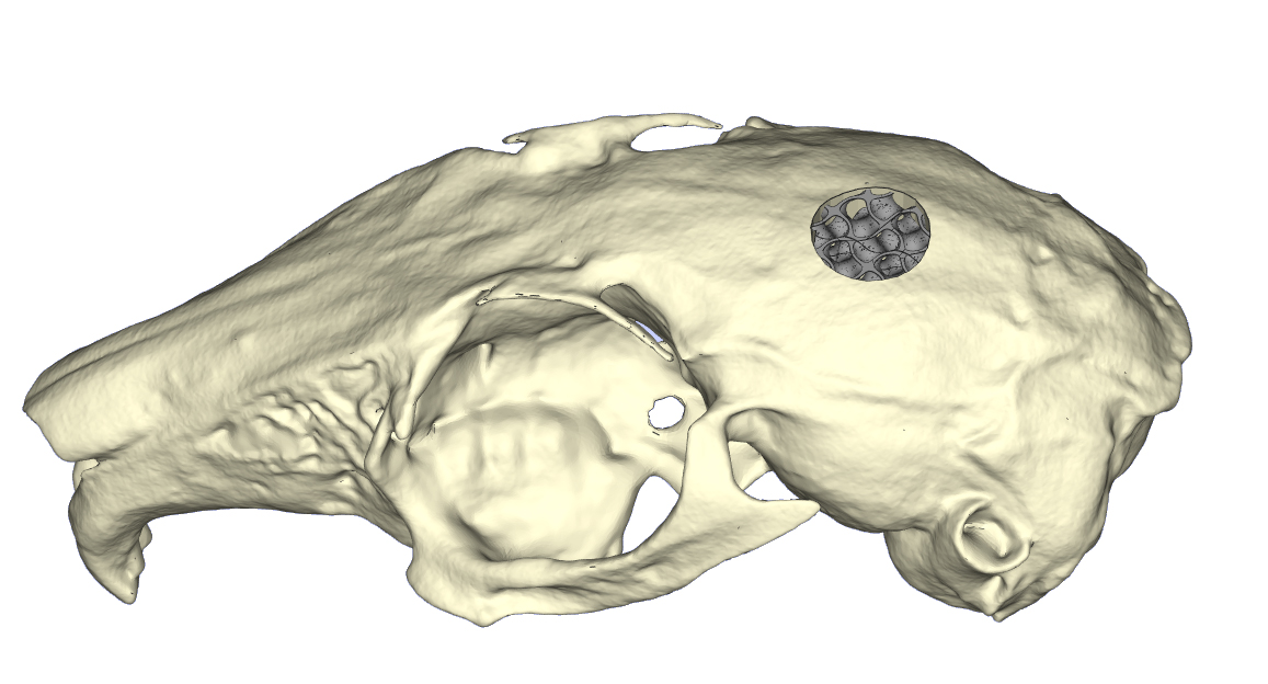
The University of Zurich went one step further and tested how well gyroids perform in vitro, in a petri dish, and in vivo, in rabbits. This study looked at three types of TPMS compared to a traditional lattice. If you decide to check out their research paper, you’ll see they refer to the gyroid shape we’ve been discussing as a diamond shape, but we’ll keep calling it a gyroid here for consistency. Of the shapes tested, the gyroid had the highest stiffness and compressive strength while having a elastic modulus comparable to bone. The gyroid shape had a statistically significant increase in the amount of tissue inside the scaffold compared to the other shapes. In a 4-week trial period the gyroid scaffold had more bone in-growth and higher bone-to-implant contact than the other TPMS shapes or the traditional lattice. The study concluded that gyroid scaffolds are promising for bone tissue applications due to the balance of mechanical properties, porosity, and low material volume.
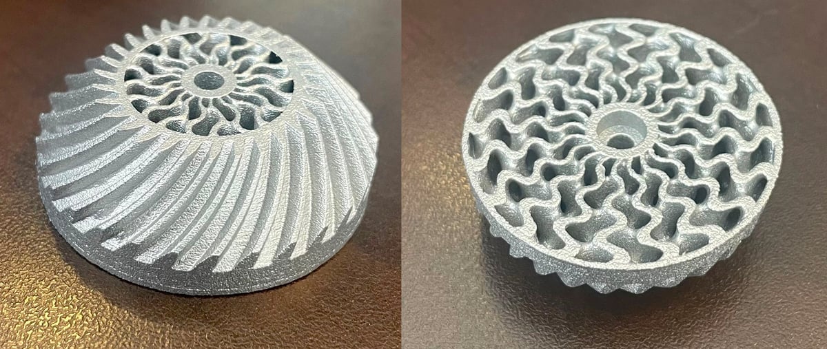
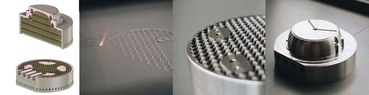
Heat Exchangers
The unique shape of the gyroid lattice, in addition to having low material volume, make it an ideal candidate for heat exchangers.
Here’s where the gyroid comes in. Researchers at the University of Glasgow used computer modeling to look at how two types of TPMS structures compare to the more traditional printed circuit heat exchangers (PCHEs). One of the TPMS structures tested was the gyroid, and the other was the Schwarz-D structure. Both types of TPMS structures performed better than the PCHE baseline. This is because both TPMS structures had more surface area for heat transfer via conduction and, more critically, both created more turbulence in the flow of gas through the heat exchanger, leading to more heat transfer via convection. Overall, both the gyroid and Schwarz-D structures outperformed the baseline structure by 15% – 100% depending on flow conditions.
Although this study was done entirely by computer simulation, it opens the door for additional studies where actual heat exchangers made with additive manufacturing can be compared to their more traditional counterparts.
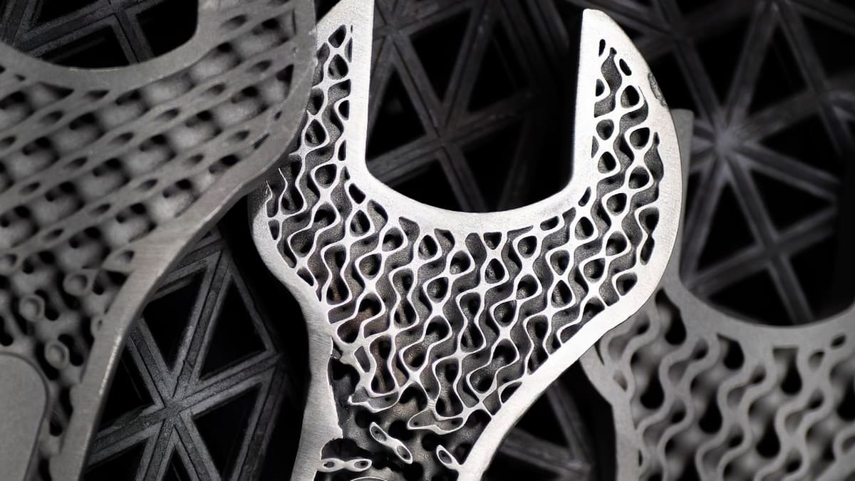
Consumer Products
There’s no shortage of consumer products that wouldn’t benefit from being lighter weight and using less material. Everything from sporting goods to kitchenware to toys could be made with less material yet function as well or better. Plus, gyroid lattices are visually appealing.
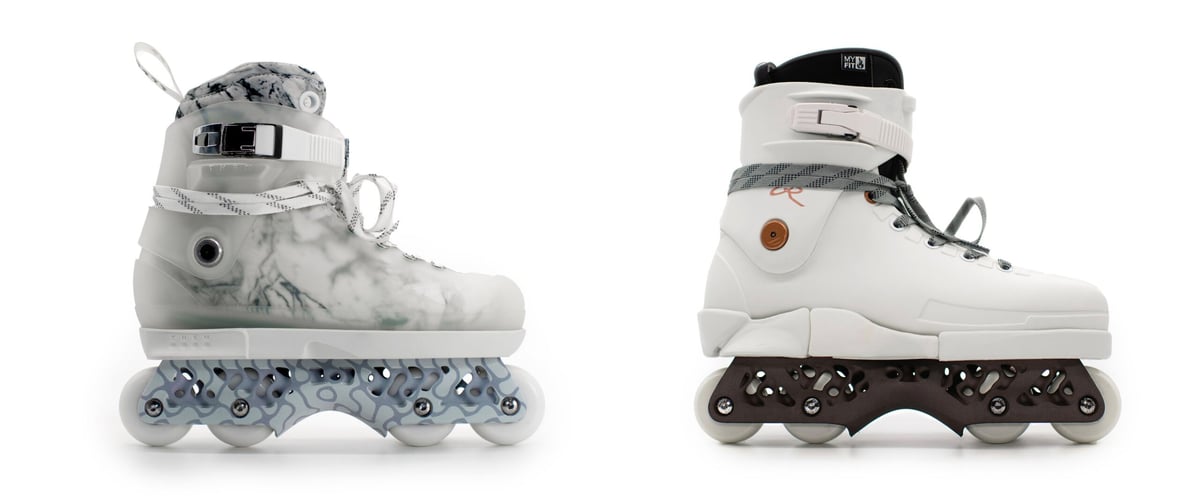
Because applying gyroid lattice structures to consumer products requires that they be 3D printed, there aren’t examples on the market yet. But in a great example of what 3D printed gyroid structures could bring to a product, like inline skates, was demonstrated by design firm Slicelab.
After getting back into skating, one of our founders of Slicelab was inspired to create something different and tailored to the type of skating he was looking for. Using nTop software, they replaced the standard, solid plastic wheel housing with a gyroid lattice one optimization for lightweighting. In the areas between the wheels where less structure was needed, a strategic gyroid system was cohesively integrated within the structure openings.
The parts were 3D printed on a HP full-color Jet Fusion 580 binder jetting machine, which is no longer in production, in nylon PA-12 material. Slicelab offers the 3MF files for free download online for people to print themselves and test out.
Software to Design Gyroid Lattices
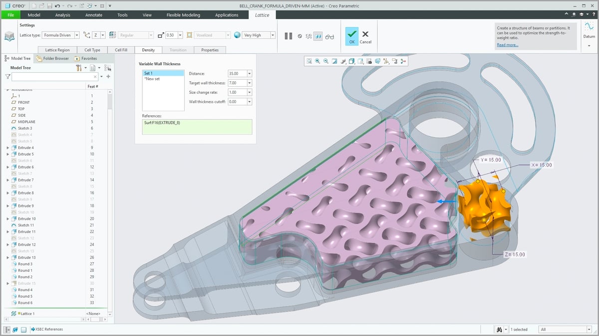
Don’t be put off by the complexity of lattices. There are some software solutions today enabling you to design with lattices with almost no previous knowledge. One new offering from BASF called the Ultrasim 3D Lattice Engine is as simple as it gets. Upload your part STL, select a lattice from the library and play around with some settings to get the properties you’re looking for, then export.
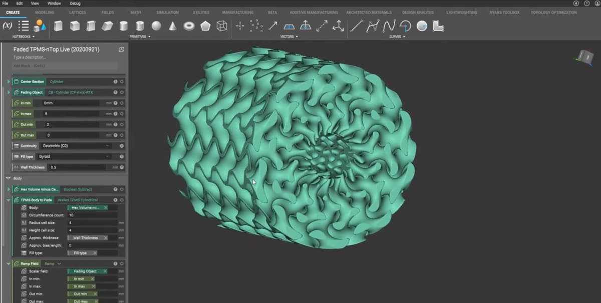
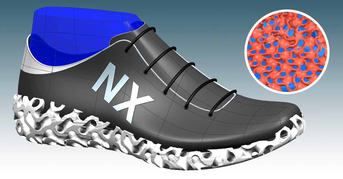
However, if you want to get more sophisticated with your lattice design, more CAD software packages are coming out to facilitate modeling gyroid lattices. Siemens NX, for example, now has an Implicit Modeling module that is geared towards engineers in the additive manufacturing space. Quick to follow suit, Autodesk Fusion 360 has a Volumetric Lattice tool through the Product Design extension. However, the premier software for designing highly organic parts for additive manufacturing is nTop, and it’s no wonder as it is also a great choice for working with gyroid lattices.
You can modeling a gyroid from scratch, but quite labor intensive. If you’re looking to build a gyroid lattice from scratch, there are tutorials available for procedural modeling software, such as Blender or Rhino. Procedural modeling allows you to input formulas into the creation of your model, which is especially handy for complex geometries like the gyroid. Also, you can model them in non-procedural software, but it’s harder to get the shape exactly right.
Gyroids and Computational Modelling
Additive manufacturing makes gyroid lattices possible. However, additive manufacturing can expensive prototype in, especially if you’re working in metal. Computation modeling, or using software simulations, is a great tool for exploring the possibilities of using gyroid lattices before you start building. In fact, the University of Glasgow’s research on heat exchangers was done completely using ANSYS CFX 15.0. Using computer software like this allows you to refine your design before getting out the checkbook to build a test part.
Files Size and Slicing
Gyroid shapes are highly organic, and this can result in huge file sizes. Generally, the more surface there is, the larger the file size. Even for more traditional lattice structures, the file size can be enormous. If you’re sending a file with a gyroid lattice off to be built, try to keep it in STP or STEP format because these formats are inherently smaller files than STL files. If you only have the part in an STL format, check that the units are correct. If the program opening the STL file reads the part as 300 inches long instead of 300mm, the file size will be much bigger. Although gyroids will result in large files, these tips will help you avoid unnecessarily adding to the file size.
The other thing to consider is slicing the file. Slicing a file with gyroid lattices is no small feat. It takes much longer compared to other lattice types and is resource intensive for the computer doing the slicing.
Software to Generate Lattice Structures
- nTop
- Altair Sulis
- Autodesk Fusion 360 & Netfabb
- Siemens NX
- Materialize 3-Matic
- Altair Optistruct & Inspire
- PTC Creo
- Carbon Design Engine
- General Lattice
- Metafold 3D
- Ultrasim 3D Lattice Engine
How to 3D Print Gyroid Lattices
Additive manufacturing has been a boon to those in academia and industry who are looking to reap the benefits of the gyroid lattice. If you’d like to explore them, read on for some best practices for incorporating gyroid lattices into your design.
Although every 3D printing technology features a layer-by-layer method, different technologies have different requirements for successful gyroid builds.
There are two primary concerns when building gyroid lattices: trapped raw material and trapped support structures.
Infill vs. Lattice
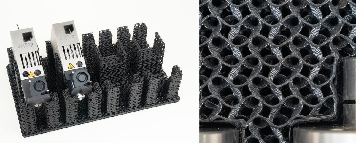
For many people, their first experience with 3D printing is fused deposition modeling (FDM) using polymer filament as the material. One big benefit of FDM is infill. When preparing to print your part, the slicing software will give you the option to apply infill. Instead of building a solid part, the middle of the part will have a lattice to save weight, material, and build time. The great thing about infill is that the slicing software makes the lattices for you, all you have to do is pick settings like density or infill wall thickness.
Popular slicing software UltiMaker Cura and PrusaSlicer both have gyroid infill options. This gives you a straightforward way to reap the benefits of gyroid structures in your parts.
Infill is specific to FDM and other extrusion-type technologies. The key factor is the parts are not surrounded by anything other than air when building. For many other types of additive technologies, parts are built surrounded by raw materials, so trying to build a part with infill would mean that it’s full of trapped resin or powder. Because of this, infill is not as often used in other types of 3D printing.
For all other 3D printing technologies, lattices — gyroid or otherwise — must be built into the model by the part designer. For the remainder of this article, I’ll be referring to lattices that are built into the model as opposed to infill, which is applied during slicing.
Raw Material Escape Plan
The first step to designing a part with a gyroid lattice is making sure that you’ve got an escape plan for the raw material. You’ll need to make sure there is access to clear the lattice.
For resin-based technologies like SLA or digital light processing (DLP), resin will be cleaned out of the parts after they’re done building so the part will need to have drain holes. Many industrial resin-based printers require a post-cure cycle after the build that locks in the final mechanical properties of the part. If there is any remaining resin, it will cure during this cycle, clogging your lattice.
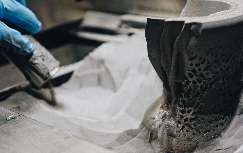
Some powder-based technologies, such as selective laser sintering (SLS) or Multi Jet Fusion (MJF) for polymers, or electron beam melting (EBM) for metals, produce part cakes. The builds come off the machine in large blocks of powder that help support the parts during the build. This powder requires compressed air or a combination of compressed air and raw powder to dislodge. These types of technologies present a challenge in building internal cavities because they require a direct line of sight for the compressed air to fully clear out the lattice. While air will swirl and eddy around inside the part, it won’t be enough to fully dislodge the powder. For SLS or MJF this might mean the final part will have loose powder inside that could be knocked free if the lattice sees fluid flow. For EBM parts, which typically require a heat treat cycle post-build, any remaining powder will solidify and clog up the lattice.
Other types of powder-based printing, such as laser powder bed fusion (LPBF), also called selective laser melting (SLM) have powder that flows loosely, like sand. Trapped powder inside a lattice is much less a concern. However, depending on the complexity of the lattice, it might take a good amount of shaking, rattling, and rolling to make sure all the powder is gone. At Protolabs, we have a special powder removal machine that does all of that for us and it does a much better job at removing powder from complex geometries than we could do manually.
Self Supporting Gyroids
Although support structures on the outside of your lattice are fine, any supports deep inside the lattice will be difficult, if not impossible, to remove. Ideally, you want your gyroid lattice to build completely free of supports. In fact, gyroids are often selected because they inherently don’t require supports, but that does depend on your application.
When you look at the gyroid lattice at an angle, it’s a series of spiraling tubes. This means that you can use the minimum unsupported channel diameter for the technology in which you’re building. Here are some general guidelines on how large the “channel” diameters can be on your gyroid lattice before requiring the use of support structures. As you exceed these recommended diameters, you’ll notice the down-facing surfaces will be rougher and rougher until the point that the top fails to grow in.
Design Gyroids to Avoid Supports
For technologies that use supports like SLA and LPBF, how the lattice stops and starts matters. When the lattice terminates with low-angled overhangs, it may require supports. However, if the lattice terminates at a point where the walls on the edge are more vertical, no supports will be needed for a successful build.
Ideally, your lattice should be walled in for the best results. If the lattice ends in a wall, the chances of it building successfully are much higher. For free standing gyroid lattices, supports on the outside aren’t the worst thing because they’re easy to access and remove. However, if you have a lattice that ends inside a part that requires supports, they’re going to be way harder, maybe even impossible, to remove.
Our Gyroid-Shaped Future
Gyroids are an incredibly useful and versatile shape that nature discovered before we did. Now that we can easily make them, we’ve brought them from being a mathematical concept into practical applications in biomechanics, energy, and more. There’s something beautifully poetic about using a nature-inspired design to help our own biology regrow tissue or reduce our environmental impact with more efficient energy production. Who knows where else the gyroid lattice will take us in the future.
About the Author:
Chloe Vollaro is a 3D printing applications engineer at Protolabs, the global digital manufacturing service provider.
License: The text of "Gyroid Lattices in 3D Printing – The Ultimate Guide" by All3DP Pro is licensed under a Creative Commons Attribution 4.0 International License.