Fusion 360 is a CAD software tool by Autodesk, a company best known for AutoCAD. Fusion 360 aims to be a well-rounded tool for all stages of the conception process, including design, manufacturing, FEA simulation, electric components, and blueprint drafting. It even allows for third-party add-ons that increase its functionality even further, allowing for things such as material planning and budgeting.
To organize all of these functions, Fusion 360 groups its tools into workspaces, of which there are seven: Design, Electronics, Generative Design, Render, Animation, Simulation, and Manufacture. Inside each workspace, you’ll find many different tabs with tools relevant to the stage of design represented by the workspace.
In this article, we’ll focus on the computer-aided manufacturing (CAM) process, and all of our work will take place in Fusion 360’s Manufacture workspace, which interprets toolpaths and exports them to G-code for a CNC machine to use. We’ll discuss everything you need to know to get started and will also touch upon some elements of the design and machining processes as they relate to Fusion 360.
360's Milling Workflow
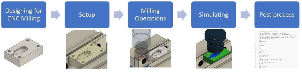
The following workflow is a simplified representation of the CAM process for CNC milling operations with Fusion 360. This is a condensed version of the detailed process suggested by Autodesk.
- Designing for the CNC milling process: The part must be modeled with a CNC mindset, taking into consideration the existing limitations of the CNC milling process, the number of operations that will be needed, as well as the tooling available for milling. For this step, you would be working in Fusion 360’s Design workspace.
- Setup: Setup is the name Fusion 360 assigns to groups of operations. You may find it under a different name if you’re using a different program. If you need to carve into two opposite faces of stock material, you’d have to configure two origin points and coordinate systems. In that case, you’d have two setups. This also translates into the physical setups you’ll have.
- Milling operations: Once you have set up a coordinate system, you have to indicate the lines in your model to be machined, called the path, and the operations used to do so. In this step, you can set the number of passes, depth of a pass, speed, and tools used. In the tutorial below, we’re going to focus on 2D milling operations, as 3D milling operations are very complex.
- Simulating: This is a crucial part of the CAM process, used to visualize the expected machining path. Here, the designer can confirm if adjustments are needed.
- Post-processing: Post-processing means generating the G-code. You should do this once you have double and triple-checked that everything is correct. When you’re in the post-processing window in Fusion 360, you have the option to choose between a lot of CNC controller firmware – GRBL or Mach3, for example. This is important because the type of controller you use can change some of the G-code. Even if your firmware isn’t listed, Fusion 360 also lets you open the G-code in its own user-friendly environment, where you can revise and manually change code if necessary. You can see the necessary code by checking your firmware’s documentation.
- Preparing the CNC Machine: Once your G-code is ready and loaded, your machine is still not ready to cut. This step is technically not done with Fusion 360, but it’s part of the overall CNC workflow. In this step, the stock of material must be placed and secured on the build plate. The zero coordinates must be established according to the position of the material, and the tool bits adjusted. Once you double and triple-check everything, you can get to machining your CNC part.
Now, we’ll go a bit more in-depth about designing and milling operations before moving on to the tutorial.
Designing for the Milling Process
In this article we focus primarily on CAM, and we’re assuming you already have some knowledge of designing for CAM. In case you don’t, you can check our article on designing for CNC. Nevertheless, here are a few important pointers to keep in mind:
If you’re primarily familiar with 3D printing, an important factor to consider when going into CNC milling is that not all shapes are suitable for CNC milling. There are not any aids like supports in CNC machining. So, when designing, you have to constantly think of how well the design can translate to the chosen manufacturing process. The resulting design must be suitable for CNC.
You also have to design keeping in mind the tools that you’ll have at your disposal. Is the material you plan to use strong enough? Do you have the necessary tool bit to achieve a certain detail? If you want chamfers, for example, you’ll need a cone-shaped tool bit, and you’ll have to physically change it during the manufacturing process.
Milling Operations
Milling operations go hand-in-hand with the tooling available. Ultimately, this is up to you and what tools you have purchased or have at your disposal. Additionally, some machines – generally larger-scale ones – can automatically change between tools, saving a lot of work and planning.
Desktop machines, however, usually require manual changes. For example, if you want to change from a ball head tool to a cone head tool, you’d have to stop the process, lift the toolhead, change the tool bit, reconfigure the zero coordinates, then run the chamfering process.
2D machining operations consist, for the most part, of simple toolpaths and operations, such as facing a part, drilling holes, or making a chamfer. The complete list can be found in section 7.4 of the Autodesk CNC machining guide.
If you want to know more about Fusion 360’s toolpaths and their uses, we recommend watching a few tutorial videos to familiarize yourself.
Tooling
The more basic the tool remains throughout the machining, the cheaper and easier it will be to manufacture. For example, a part requiring five or six specialized insert form mills will be considerably more difficult and more costly to machine than a part requiring three or four basic mills.
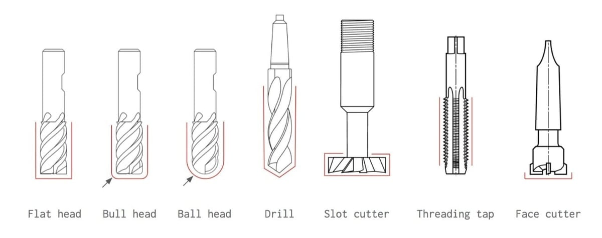
There are many kinds of end mills or “bits” for CNC. These are some of the basic ones:
- Flathead, bullhead, and ball head: Used to machine slots, grooves, cavities, and other vertical walls, the geometries of these end mills let programmers machine the majority of parts. For example, a 3D parallel operation in combination with a ball head mill can create a complex 3D surface.
- Drills: Common and quick, these end mills work well for creating pass-through holes and holes that will later require threading. For more precise holes that will house a bearing or other precision components, reaming or boring operations can do the job.
- Slot cutters: These allow for T-slot milling as well as other undercuts that need to be made on the part.
- Threading taps: Commonly used for, you guessed it, threading holes. Each tap has a corresponding thread, so designing a part with mostly the same thread sizing throughout is recommended.
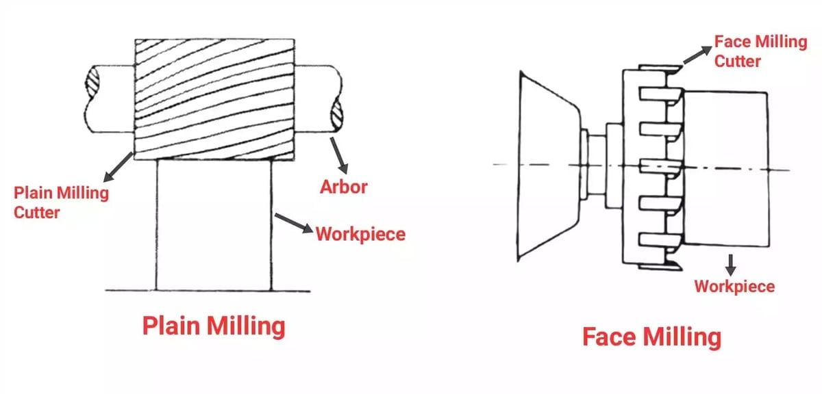
- Face milling cutters: These end mills “face” stock materials to the wanted dimensions. They’re commonly used to remove material from large flat surfaces. They have considerably larger diameters than flathead mills to optimize material removal rates.
CAM Tutorial
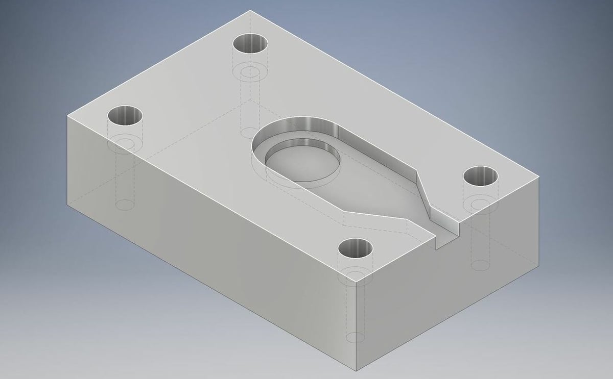
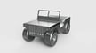
Now that we’ve been through the general process, we’re going to create a program for the part in the above image. This is a real part that houses a special temperature sensor in its center.
For this, we’re only going to machine one face of the part. The part will be made of Aluminum 6061, and the stock has been pre-cut to size, which means that we only need to machine the upper face and the features contained within. Also, as we’re working with aluminum, high-speed steel mills can be used, reducing the machining costs.
Finally, the part geometry was designed under the rules of thumb listed previously, which means machining will be fairly easy.
Setting Up
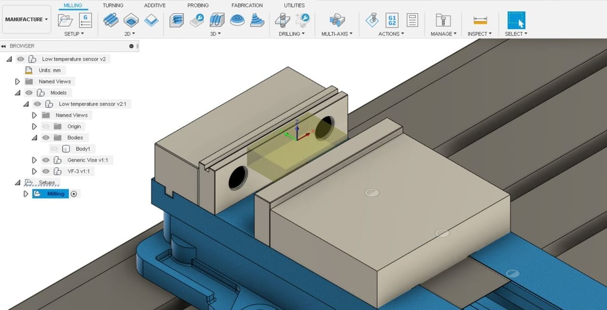
As we only need to machine the upper face of the part, only one setup will be needed. Once in the manufacturing tab, click “Milling > Setups > New Setup”. This is where we let Fusion 360 know the stock dimensions, how we’re going to hold the material, and where the Work Coordinate System is:
- Raw stock: Always pick stock material dimensions that match the stock material dimensions in real life.
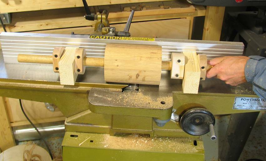
- Holding the stock material: We’ll be using a single jaw vise for the job, which is standard in today’s CNC milling. The sensor housing needs to be milled in the center. Therefore, clamping the part from the sides is necessary to have a safe workspace and to ensure stability.
- Work Coordinate System (WCS): This coordinate system will need to be dialed into the machine, and keeping it simple helps a lot. In this example, the center point of the stock is chosen, as it’s a symmetric point on the part that’ll be easy for a CNC operator to dial into the machine. For more on WCS, you can read Autodesk’s guide.
Tool Input
This is a crucial step where you have to make sure that the real physical cutting tools you’ll be using during the machining process are also loaded in the Fusion 360 list. Positions of the path depend on the tools’ diameter and material. If tools aren’t already listed, you can add them manually.
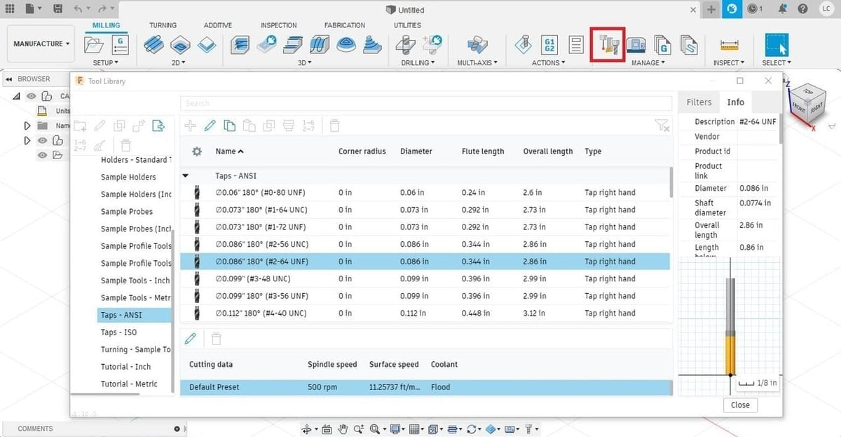
Open the CAM Tool Library, which you can find in the “Manage” section of each tab. You can see the existing tools listed, and by selecting one of them, you can get a preview of the dimensions on the right side of the window.
New tools can be added by selecting the “Add new” button on the top left. Fusion 360 uses visual aids to indicate specifications such as diameter, number of threads, and length of the thread, among others.
Milling Operations
At this point, we have to choose which toolpath operations to perform in order to reach our desired geometry. We’ll break down the five operations needed to machine this part below, but before you execute them, each milling operation will need to be set up.
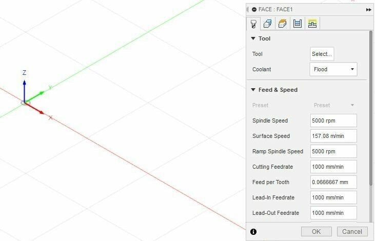
A window with setup details will open. You should proceed as follows:
- Choose a tool that suits the operation.
- Enter the speeds and feed rates under the first tab (“Tool”).
- Select the geometry you want to machine under the second tab (“Geometry”).
- Choose the heights of the planes under the third tab (“Heights”).
- Select the toolpath behavior in the fourth (“Passes”) and fifth (“Linking”) tabs.
The Operations
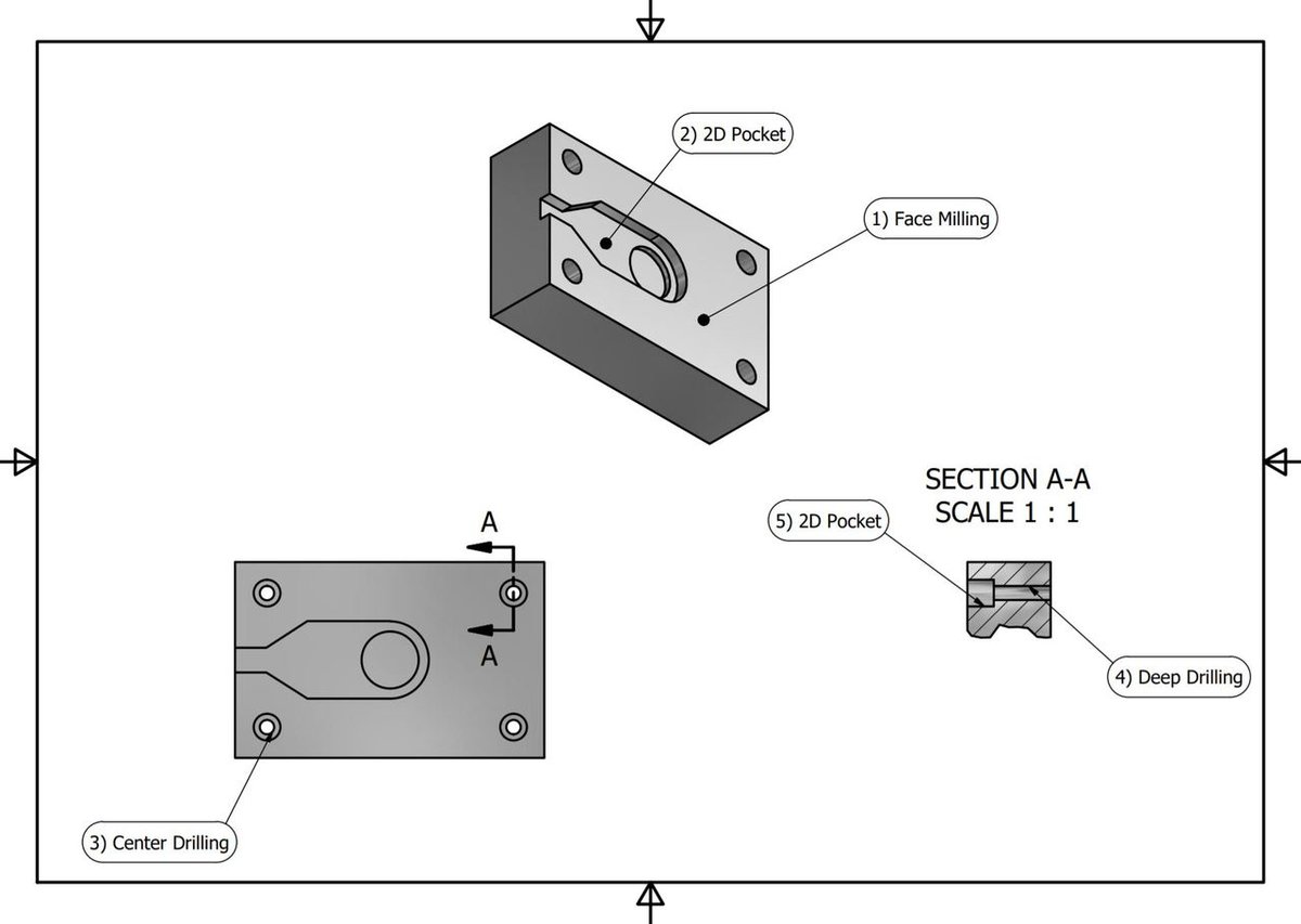
To achieve our part, we’ll define the following toolpath operations in this order:
Face Milling
- Under 2D operations, choose “Face”.
- Select a face mill diameter that suits your needs. In our case, we’ll select one that covers the whole piece in one pass.
- Choose the part’s face where the face mill will work.
- Click “OK”.
2D Pocket Milling
- Under 2D operations, choose “2D Pocket”.
- Choose a tool that’ll easily fit in the pocket. Usually, a flathead mill will do the job.
- Select the pocket contours you’d like to machine. On this part, we’ll click on the outside contour of the pocket as well as the rounded inner pocket contour.
- Click “OK”.
Center Drilling
- Under drilling operations, choose “Drill”.
- Select a center mill. This will serve as a guide for the deep drilling that comes next.
- Select the geometry of the holes and, under the “Cycle” tab, select the drilling operation needed. In this case, “Drilling – Rapid out” is suitable.
- Click “OK”.
Deep Drilling
- Under drilling operations, choose “Drill”.
- This time, choose a drill that can do the job.
- Choose the right drilling operation needed under the “Cycle” tab. In this case, “Deep Drilling – Rapid out” is best.
- Click “OK”.
2D Pocket Milling
- Under 2D operations, choose “2D Pocket”.
- Select the bolt head housing geometry.
- Click “OK”.
Tip
When you’re drilling, for example, the tool drills the center of the marked point, obviously. But if you’re doing contouring, you have to indicate if you want your tool to pass in the center, outside, or inside – which affects the dimensions of the final result. In this tutorial, we don’t do any operation where this is necessary, but it’s good to know for future projects.
Simulating
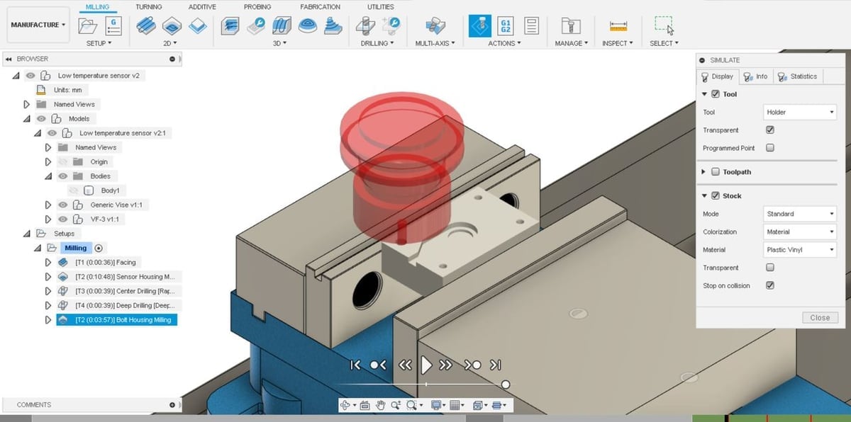
This is where Fusion 360 really shines, showing machine crashes and stock collisions. This can help save thousands of dollars’ worth of machine repairs and tool replacements.
In the image, we can see that a crash happened on the last operation due to a mill “lead out”, which creates a radius lead out instead of a straight Z retraction, causing the whole flat end mill to rapidly collide with the stock on the way out.
The Fusion 360 simulation space can be opened by clicking a setup or an operation and selecting “Simulate”. When the “Stop on Collision” option is enabled, the simulated toolhead will stop and highlight in red where a collision occurs.
Jumping between simulations and tweaking operations can help a lot to find optimization points, saving you from mistakes, reducing program lines, and ultimately saving time.
Post-Processing
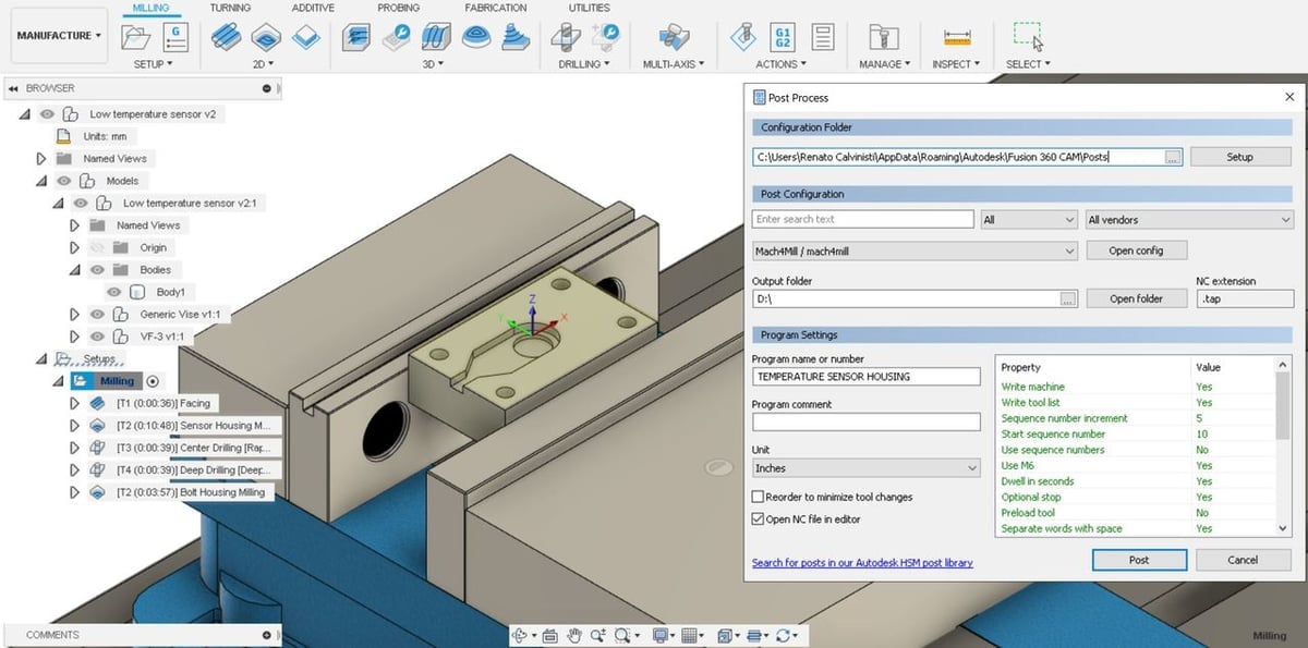
CNC mills operate using a machine language called G-code. In order to export the operations to G-code, click on the setup and select “Post Process” above the “Actions” dropdown menu.
Alternatively, you can repeat the process above while selecting individual operations if the goal is to export them separately. In the post-processing window, units (inches or millimeters) for the program can be defined as well as the name of the program, the program properties and values, and the machine’s specific post-processor.
We recommend leaving the “Open NC file in editor” option checked so that the generated G-code is given a final revision.
Preparing the CNC Machine
Once the entire CAM process is ready, you have to set up your machine. The saying in the CNC community goes “Measure twice, cut once”. Once you start cutting, there’s no undoing it. Plus, you don’t want to waste materials or damage the cutting tools.
The process of preparing the CNC machine usually consists of the following:
- Locate and secure your stock of material on the build plate in such a way that it can’t move during the cutting process.
- Set up the zero coordinates in accordance with what you set them as in Fusion 360.
- Without a cutting tool, run the program to verify it’s performing all the desired operations within the bounds of the material and the machine.
- Introduce the tool bit you’re going to use for your process. If you’ll be changing toolheads, this process will probably be repeated multiple times.
- Set up the zero coordinates once again, this time taking into account the height of the tool bit when setting up the Z coordinate.
And you’re all set to go! But remember, it’s always better to double-check before hitting start!
License: The text of "Fusion 360 CAM: A Starter Guide to Fusion 360 for CNC" by All3DP Pro is licensed under a Creative Commons Attribution 4.0 International License.